A transparent roof with photovoltaic panels

A photovoltaic panel and transparent technology, applied to roofs using tiles/slate tiles, roofs using flat panels/curved panels, and support structures for photovoltaic modules, etc., can solve problems such as the loss of sun visor functions, achieve brightness changes, and facilitate Opening and closing, power saving effect

Active Publication Date: 2018-10-12
邱丹敏
View PDF11 Cites 0 Cited by
  • Summary
  • Abstract
  • Description
  • Claims
  • Application Information

AI Technical Summary

Problems solved by technology

For example, in the existing architectural design, a window is set on the roof and a sealed transparent glass plate is laid, so that the above can look up at the starry sky when sleeping, and in order to prevent direct sunlight from entering the room during the day, the windows on the roof are generally equipped with automatically controlled sunshades Commonly used sun visors are generally controlled by electricity, and a corresponding circuit control structure needs to be built to connect with the household circuit. When the household circuit is powered off, the sun visor will lose its corresponding function.

Method used


Image

  • A transparent roof with photovoltaic panels
  • A transparent roof with photovoltaic panels
  • A transparent roof with photovoltaic panels

Examples


Embodiment Construction

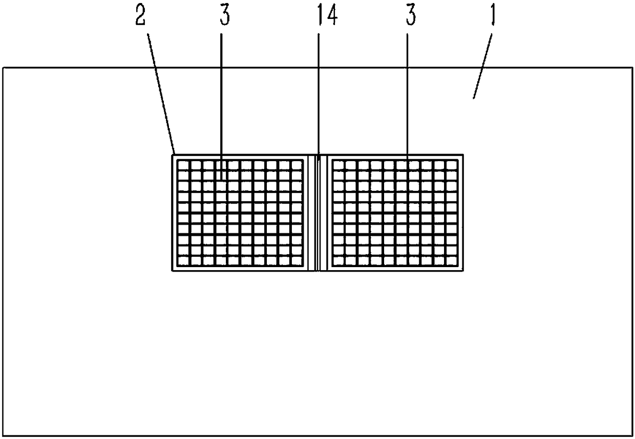
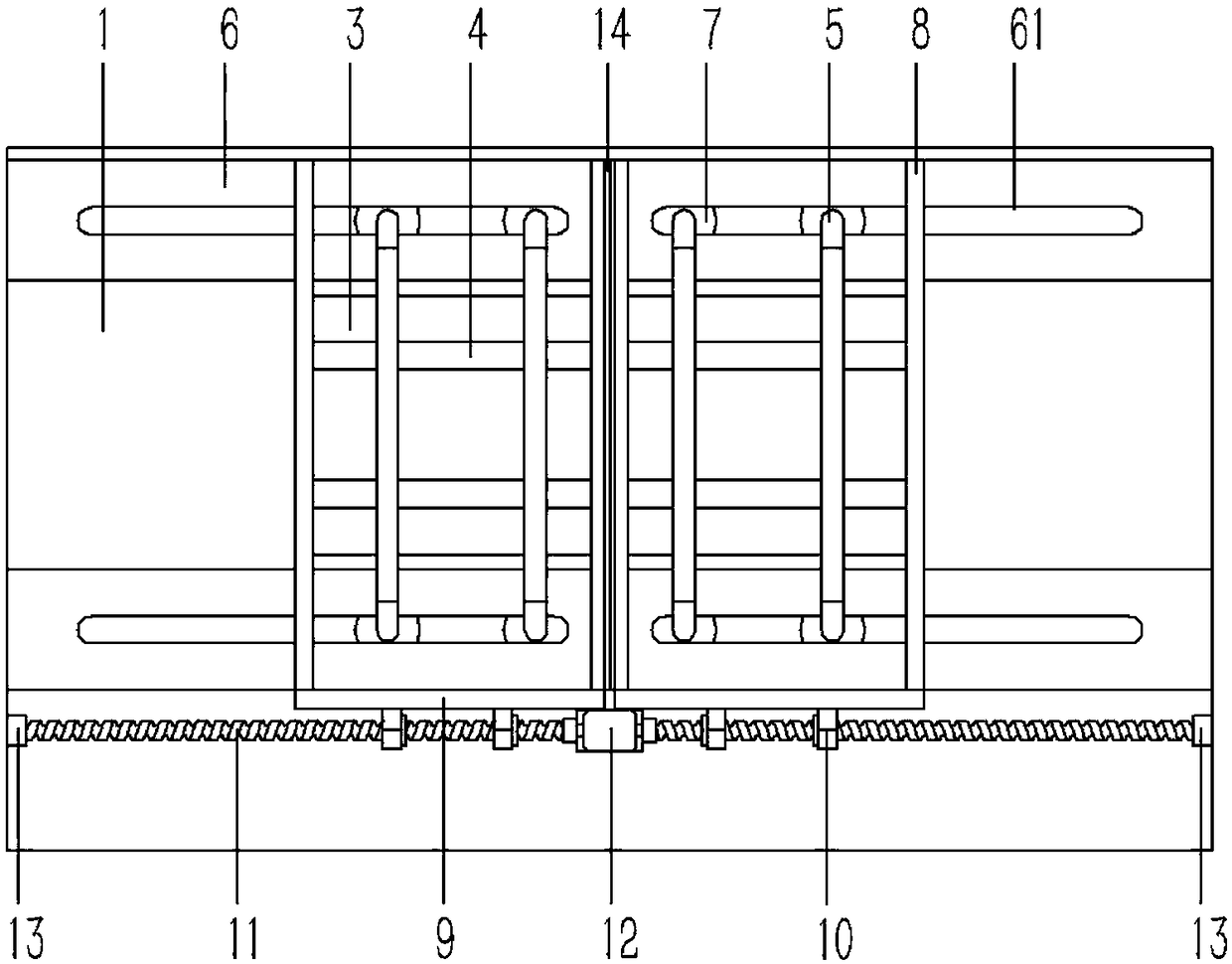
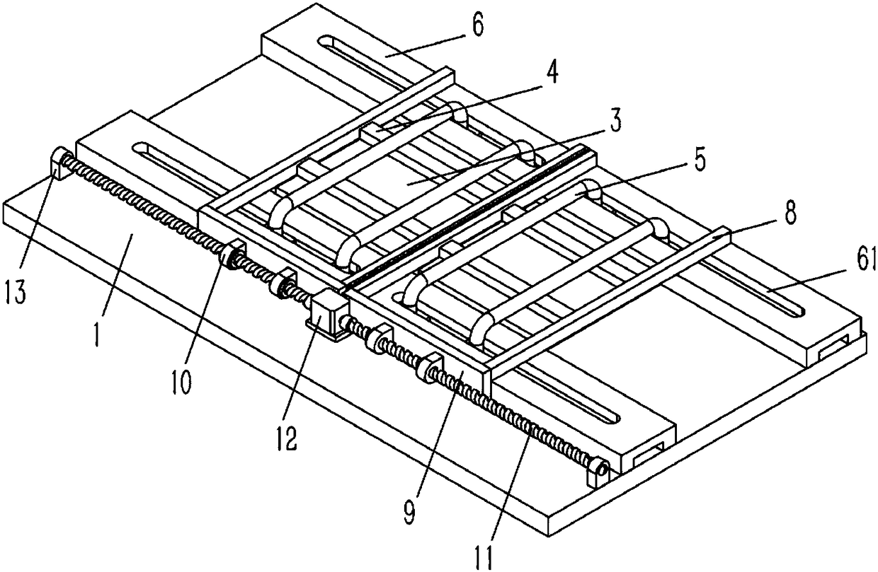
[0017] Example: see Figures 1 to 3 As shown, a transparent roof using photovoltaic panels includes a ceiling 1, a window is opened on the ceiling 1, a transparent glass 2 is installed in the window of the ceiling 1, and two photovoltaic panels 3 are arranged directly below the transparent glass 2. The ceiling 1 on the front and rear sides of the panel 3 is fixed with a "匚"-shaped groove rail 6, and guide grooves 61 are formed on the left and right sides of the groove rail 6, and the photovoltaic panel 3 is fixed on several horizontal channel steel 4, the channel steel 4 is fixed on several longitudinal round steel 5, and the two ends of the round steel 5 are bent to form vertical poles, and the poles of the round steel 5 pass through the guide groove 61 of the groove rail 6 and are hinged with rollers. 7. The roller 7 is plugged into the groove rail 6;

[0018] The two ends of the channel steel 4 are fixed on the longitudinal connecting rod 8, and the connecting rod 8 on the...


PUM


Abstract

The invention discloses a transparent roof employing photovoltaic plates, and the roof is provided with a window. The interior of the window is provided with transparent window, and two photovoltaic plates are disposed exactly below the transparent glass. The ceilings at the front and rear sides of the photovoltaic plates are fixedly provided with grooved rails, and the left and right sides of the grooved rails are provided with guide grooves. The photovoltaic plates are fixed on a plurality of lateral box irons, and the box irons are fixed on a plurality of longitudinal round steels. Two ends of the round steels are bent into fulcrum bars, and the fulcrum bars pass through the guide grooves of the grooved rails to be hinged to rollers. The rollers are inserted into the grooved rails. Two ends of the box irons are fixed on longitudinal connecting rods, and connecting rods of the photovoltaic plates are fixed on the lateral side plates. The lateral side plates abut against the side walls of the grooved rails, and the side plates are fixedly provided with a plural of supporting lugs. The supporting lugs are in screwed connection with lateral screw rods through linear bearings, wherein one end of each screw is fixedly connected with a rotating shaft of a motor through a shaft coupler, and the other end of the screw is hinged to a bearing seat. The photovoltaic plates are used for replacing a sun shield, so the roof can achieve the independent power supply, and facilitates the opening and closing of a transparent window of the roof.

Description

Technical field: [0001] The invention relates to the technical field of photovoltaic panels, in particular to a transparent roof using photovoltaic panels. Background technique: [0002] At present, with the progress of society and the improvement of people's material level, the requirements for quality of life are getting higher and higher. For example, in the existing architectural design, a window is opened on the roof, and a sealed transparent glass plate is laid, so that the above can look up at the starry sky when sleeping, and in order to prevent direct sunlight from entering the room during the day, the windows on the roof are generally equipped with automatically controlled sunshades. Commonly used sun visors are generally controlled by electricity, and a corresponding circuit control structure needs to be built to connect with the household circuit. When the household circuit is powered off, the sun visor will lose its corresponding function. Invention content: ...

Claims


Application Information

Patent Timeline
Patent Type & Authority Patents(China)
IPC IPC(8): E04D13/035E04D13/18H02S20/26
CPCE04D13/00E04D13/035H02S20/26Y02B10/10Y02E10/50
Inventor 赵鸿斌
Owner 邱丹敏
Why Eureka
Try Eureka