
Thermostatic valve with sleeve

A thermostatic valve and sleeve technology, applied in the field of thermostatic valves, can solve problems such as stress application and valve failure

Active Publication Date: 2018-10-12
VERNET SA
View PDF15 Cites 0 Cited by
  • Summary
  • Abstract
  • Description
  • Claims
  • Application Information

AI Technical Summary

Problems solved by technology

However, such an arrangement can lead to failure of the valve when, especially in the case of mishandling or shocks during installation or maintenance of the valve, considerable stress is exerted on the bracket and causes compression of the spring: the risk is that the bracket will partially or completely Separated from the supporting part of the housing

Method used


Image

  • Thermostatic valve with sleeve
  • Thermostatic valve with sleeve
  • Thermostatic valve with sleeve

Examples


Embodiment Construction

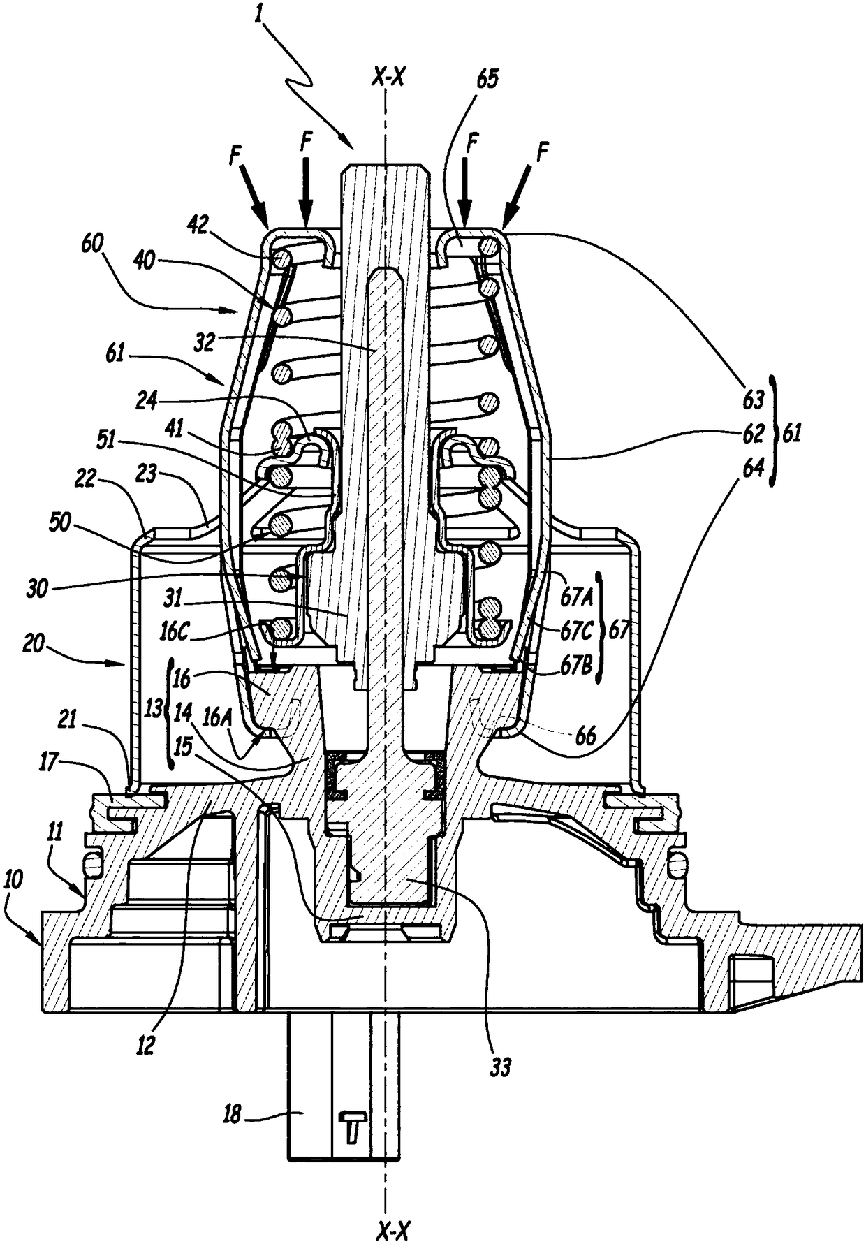
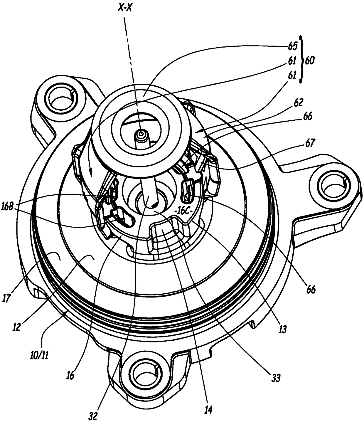
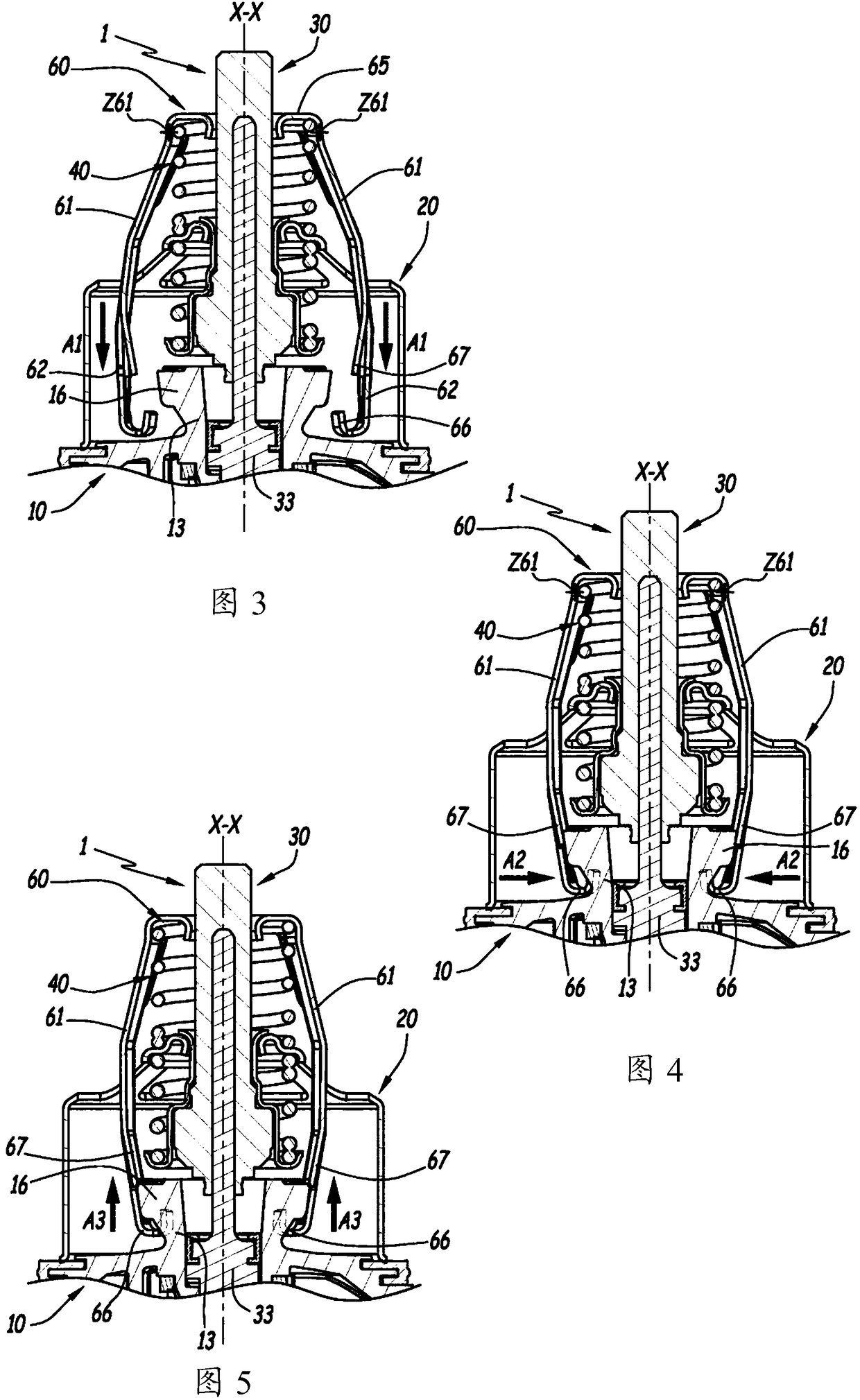
[0034] Figure 1 to 5 A valve 1 suitable for controlling the circulation of fluid is shown. For example, the valve 1 is used for the cooling cycle of the heat engine of the vehicle.

[0035] The valve 1 includes a housing 10 in which the fluid mentioned above circulates. The housing 10 is especially made of plastic, for example by moulding. In the embodiment considered here, such as figure 1 with 2 It is clearly shown that the housing 10 includes a main body 11, and the main body 11 includes a closed wall 12 separating the inner and outer sides of the main body 11. Except in the case of abnormal leakage, the fluid regulated by the valve is only in the closed wall 12 Flow inside. Such as figure 1 It is clearly shown that the closing wall 12 extends transversely to the geometric axis X-X, which belongs to figure 1 For convenience, adjust the rest of the description relative to the geometric axis X-X, so that the axis X-X extends along the vertical inner side of the main body 11, ...


PUM


Abstract

The invention relates to a thermostatic valve (1) comprising: a housing (10); a sleeve (20) for controlling the flow of fluid in said housing, said sleeve being able to move along its axis (X -X) movement; a thermostatic element (30), due to the expansion of the thermally expandable material of the element, the movable part (31) of the thermostatic element can be moved along the axis relative to the fixed part of the thermostatic element ( 32) movement to move the sleeve; a compression spring (40) for returning the fixed portion and the movable portion toward each other; and a bearing ring (60) for the spring, in During operation said bearing ring is subjected to a reduced pressure produced by said spring, said bearing ring is provided with means (66) for attachment to a bearing surface (13) of the housing transverse to said axis, said attachment means engages with said bearing surface in a form-fitting manner to hook on said bearing surface along said axis due to a decompression force generated by said spring, and said bearing ring is provided for axially abutting said Means (67) for locking the loop in place while supporting the surface to keep the attachment means hooked on the bearing surface when a load (F) for compressing the spring is applied to the loop .

Description

Technical field [0001] The present invention relates to a thermostatic valve, especially a thermostatic valve used in a fluid circulation circuit, especially a thermostatic valve used in a cooling liquid of a heat engine. Background technique [0002] The valve is provided with an adjustment sleeve for the circulation of fluid, the movement of the adjustment sleeve is controlled by a thermostatic element, which is usually equipped with a large displacement heat engine (especially for trucks or some motor vehicles) associated A cooling circuit in which a large-displacement heat engine requires a higher coolant flow rate to operate compared to the coolant flow rate encountered by a heat engine with a smaller displacement and the thermostatic valve used usually has a gate. [0003] In fact, the use of sleeves usually makes it possible to have a so-called balanced shutter (ie, the following shutter), for which shutters are generally present on either side of the wall of the sleeve in t...

Claims


Application Information

Patent Timeline
Patent Type & Authority Patents(China)
IPC IPC(8): G05D23/02
CPCF01P7/16G05D23/022F16K31/025F01P7/00
Inventor 奥德·波斯特纳科蒂埃里·马罗
Owner VERNET SA
Learn More