Building waste crushing apparatus

A crushing device and construction waste technology, applied in the field of construction machinery, can solve the problems of unsorted metal, incomplete crushing, large structure, etc., and achieve the effect of easy operation, thorough crushing, and convenient crushing

Active Publication Date: 2017-05-10
JIANGSU VOCATIONAL INST OF ARCHITECTURAL TECH
View PDF8 Cites 20 Cited by
  • Summary
  • Abstract
  • Description
  • Claims
  • Application Information

AI Technical Summary

Problems solved by technology

[0002] At present, the amount of construction waste in my country has accounted for 30%-40% of the total amount of urban waste. Construction waste includes waste generated during construction and house demolition. However, most of the construction waste has not been treated. It is transported to the suburbs or villages by the construction unit, and it is stacked in the open air or landfilled. However, when cleaning the garbage, the garbage must first be crushed so as to be shipped. sorted out, resulting in waste

Method used


Image

  • Building waste crushing apparatus
  • Building waste crushing apparatus
  • Building waste crushing apparatus

Examples


Embodiment 1

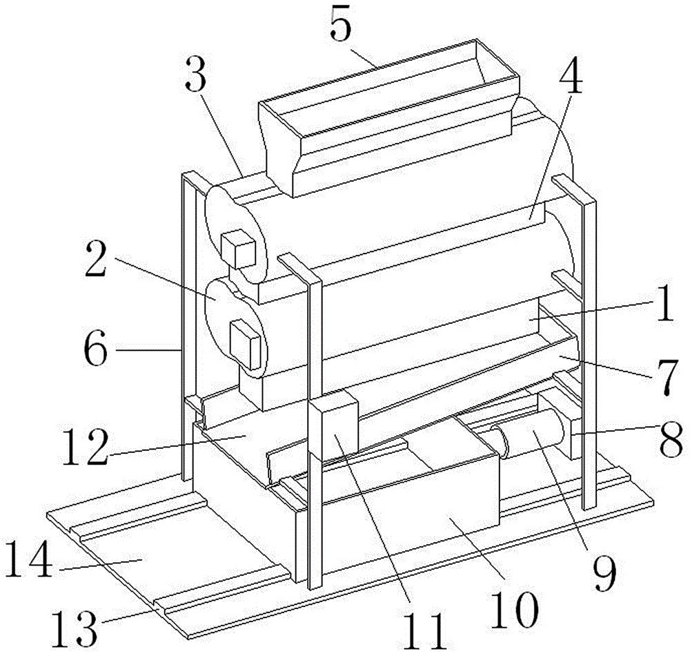
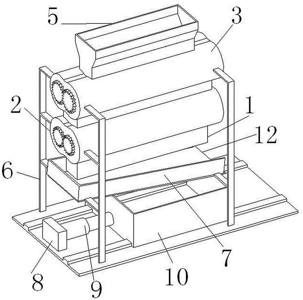
[0025] A construction waste crushing device, comprising a bottom plate 14, two corresponding support frames 6 are arranged on the upper surface of the bottom plate 14 close to two opposite long sides, and there is a primary crushing device between the upper ends of the four support frames 6 3.

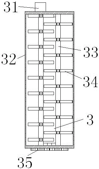
[0026] The primary crushing device 3 comprises a first crushing shell 32 and two rotating shafts 33; the upper end of the first crushing shell 32 is provided with a feeding port, and the upper end of the charging port is provided with a feeding chute 5, and construction waste can be fed from the feeding chute. 5 into the first crushing shell 32, the lower end of the first crushing shell 32 is provided with a discharge port; two rotating shafts 33 are installed in parallel in the first crushing shell 32, and the two ends of the rotating shaft 33 are respectively supported by a bearing on the On the first crushing shell 32; each of the two rotating shafts 33 is provided with mutually sta...

Embodiment 2

[0031] On the basis of Embodiment 1, the lower end of the discharge chute 1 is provided with an electromagnetic plate 12, the metal in the crushed construction waste can be absorbed by the electromagnetic plate 12, and a 15 is provided between the electromagnetic plate 12 and the upper surface of the bottom plate 14 -25 degrees of bevel, and around the upper surface of the electromagnetic plate 12 is provided with a frame 7, through the frame 7 can prevent the crushed construction waste from running out from the side, and the frame 7 at the lower end of the electromagnetic plate 12 is provided with an opening, and the electromagnetic The both sides of plate 12 are connected with support frame 6 by connecting column, and the output end of control switch 11 is electrically connected the input end of electromagnetic plate 12, and the input end of control switch 11 is electrically connected the output end of external power supply, and the upper surface of bottom plate 14 is provided...


PUM


Abstract

The invention discloses a building waste crushing apparatus, comprising a bottom plate; four supports are arranged on the upper surface of the bottom plate; a primary crushing unit is arranged among the upper ends of the four supports, the upper end of the primary crushing unit is provided with a feed port, the upper end of the feed port is provided with a feed trough, a first motor is arranged on one side of the primary crushing unit, and the lower end of the primary crushing unit is provided with a discharge port; it is possible to crush bulky waste through the primary crushing unit so that crushing is more convenient; a secondary crushing unit is arranged below the primary crushing unit; it is possible to crush the waste thoroughly through the secondary crushing unit so that crushing is more thorough; it is possible to attract metals in the crushed waste through an electromagnetic plate so that the metals can be recycled; the building waste crushing apparatus is simple in structure and simple to operate, and is capable of crushing waste thoroughly and sorting the metals in the waste in order to collect and reuse the metals.

Description

technical field [0001] The invention relates to the technical field of construction machinery, in particular to a construction waste crushing device. Background technique [0002] At present, the amount of construction waste in my country has accounted for 30%-40% of the total amount of urban waste. Construction waste includes waste generated during construction and house demolition. However, most of the construction waste has not been treated. It is transported to the suburbs or villages by the construction unit, and it is stacked in the open air or landfilled. However, when cleaning the garbage, the garbage must first be crushed so as to be shipped. Sorted out, resulting in waste. Contents of the invention [0003] The technical problem to be solved by the present invention is to overcome the existing defects and provide a construction waste crushing device, which is simple enough and easy to operate. It can not only completely crush the waste, but also sort out the metal...

Claims


Application Information

Patent Timeline
Patent Type & Authority Applications(China)
IPC IPC(8): B02C4/08B02C18/14B02C23/10B03C1/02
CPCB02C4/08B02C18/0092B02C18/142B02C23/10B02C2201/06B03C1/02
Inventor 付红仇文宁赵武范玉张海燕黄继战解恒参苗磊刚国芳崔廷峰周磊涂强
Owner JIANGSU VOCATIONAL INST OF ARCHITECTURAL TECH
Why Eureka
Try Eureka