
A multi-axis ankle prosthesis with spherical structure and adjustable joint axis angle
A joint axis and adjustable technology, applied in the field of bionic human prosthetics, can solve the problems of low degree of personalized fit, uncoordinated gait, large overall size of prosthetics, etc., to improve the complex structure, increase the bearing capacity, and make the structure simple enough Effect
- Summary
- Abstract
- Description
- Claims
- Application Information
AI Technical Summary
Problems solved by technology
Method used
Image

Examples
Embodiment Construction
[0053] Describe the present invention below in conjunction with accompanying drawing.
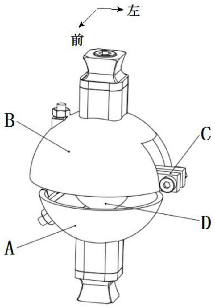
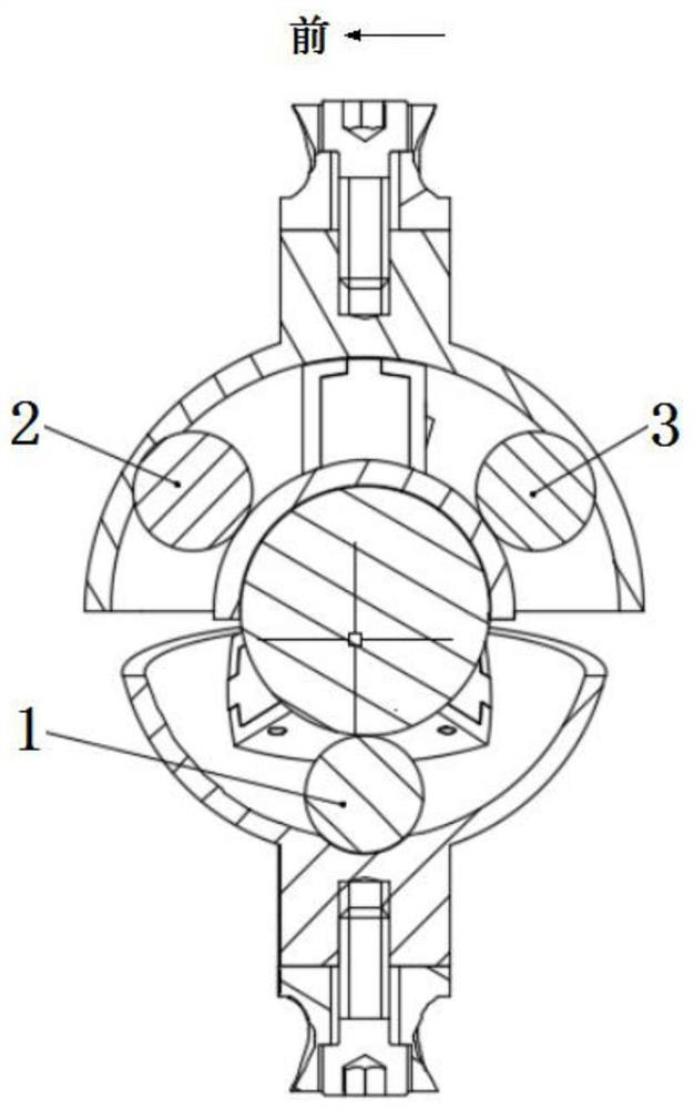
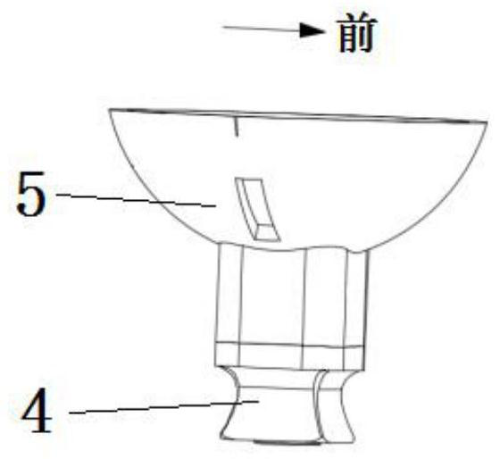
[0054] Such as figure 1 , figure 2 , Figure 26 , Figure 27 As shown, the present invention is composed of a foot connecting part A, a leg connecting part B, an upper part C, a lower part D, a ball I1, a ball II2, a ball III3 and an auxiliary plate 42, wherein the foot connecting part A, the lower part D, the upper part C and the legs are connected Part B is arranged sequentially from bottom to top; the boss I22 of the slider assembly IE in the upper part C is located in the elongated chute IIf of the upper cover 7 in the leg connection part B, and the boss I22 is in clearance fit with the elongated chute IIf; the upper part The threaded rod I21 of the slider assembly IE in C passes through the long chute IIf of the upper cover 7 in the leg connection part B, and is fixed by a nut; the boss II36 of the slider assembly IIG in the lower part D is located in the foot connection part A In...
PUM
 Abstract
Description
Claims
Application Information