Electric hammer support for building punching

A technology for hole use and electric hammer, which is applied in the direction of striking tools, light impact tools, manufacturing tools, etc. It can solve the problems of limited use of two hands, low work efficiency, and poor safety, so as to reduce manpower work, improve efficiency, and improve The effect of work efficiency

Pending Publication Date: 2017-05-10
陈晶晶
View PDF0 Cites 0 Cited by
  • Summary
  • Abstract
  • Description
  • Claims
  • Application Information

AI Technical Summary

Problems solved by technology

[0002] In installation engineering and decoration engineering, the installation of fire-fighting pipelines, cables, optical cables, ceilings, electric lights, etc. in the house requires drilling on building components and building materials. The vertical direction of existing building components and building materials Drilling work is mostly carried out by manual hand-held electric hammer through crawling ladders, scaffolding, etc. After drilling a component, it is necessary to move the position of the ladder, scaffolding, etc. to proceed to the next component. Due to the high-altitude drilling It is always operated by one person, and the use of both hands is limited. It is very troublesome to place the electric hammer from time to time, and the work efficiency is low, the safety is poor, and it is a waste of manpower. Each work requires multiple manpower to assist. Inconvenient, for this reason, we propose an electric hammer bracket for construction drilling

Method used


Image

  • Electric hammer support for building punching
  • Electric hammer support for building punching
  • Electric hammer support for building punching

Examples


Embodiment Construction

[0015] The following will clearly and completely describe the technical solutions in the embodiments of the present invention with reference to the accompanying drawings in the embodiments of the present invention. Obviously, the described embodiments are only some, not all, embodiments of the present invention.

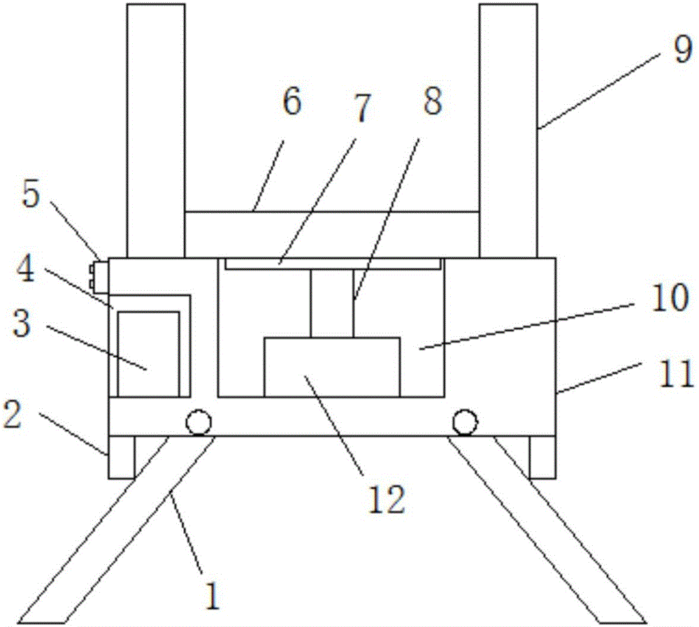
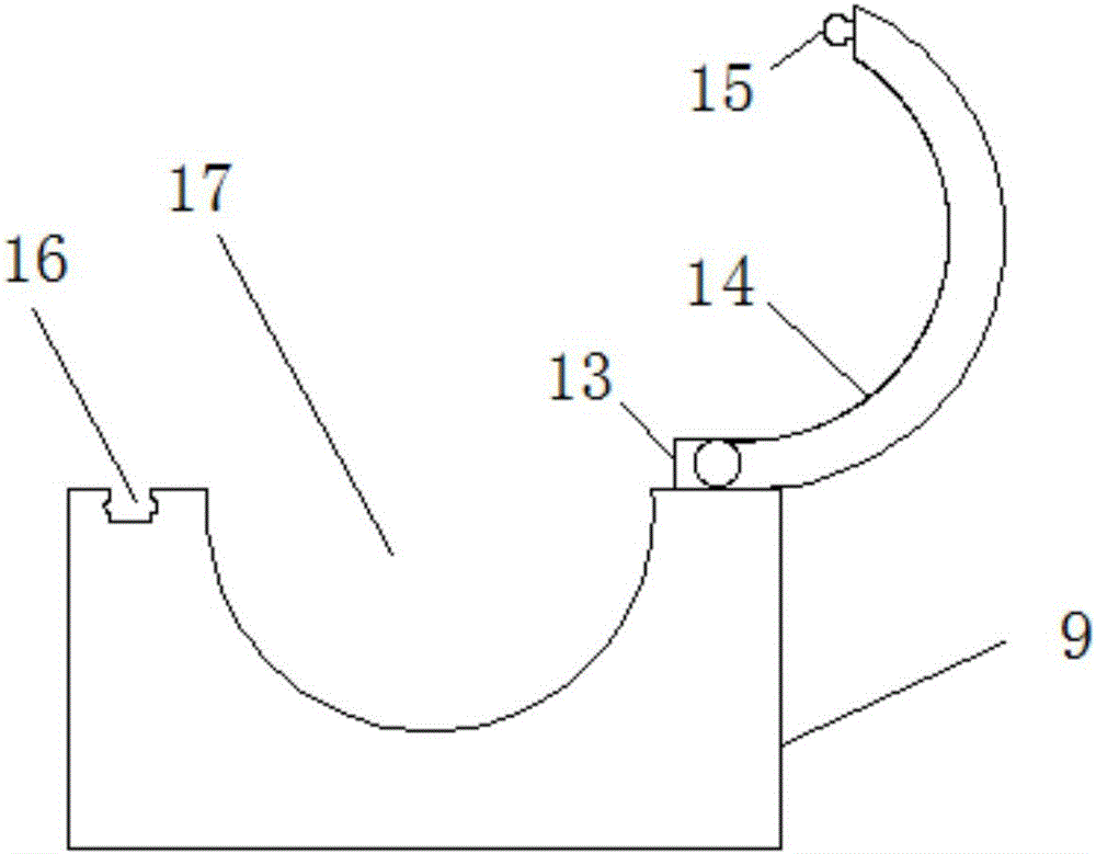
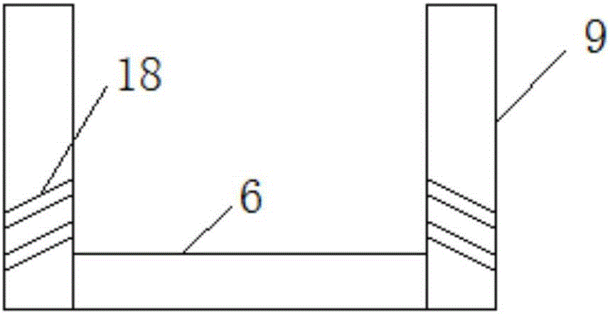
[0016] refer to Figure 1-3 , an electric hammer bracket for building holes, comprising a base 11, the two sides of the lower end of the base 11 are symmetrically provided with stoppers 2, both sides of the lower middle of the base 11 are movably connected with support rods 1 through pin shafts, and the upper end of the base 11 Bonded with a shock absorber, in order to reduce friction and increase service life.

[0017] Two support rods 1 are located between two stoppers 2, a control switch 5 is installed on the outside of the base 11, a first groove 4 is opened on one side of the base 11, a power supply 3 is installed in the first groove 4, and a power supply 3 It ...


PUM


Abstract

The invention relates to the technical field of electric hammer supports, in particular to an electric hammer support for building punching. The electric hammer support comprises a base, a first groove is formed in one side of the base, a power source is electrically connected with a control switch, a second groove is formed in the middle of the upper end of the base, and the bottom end of the second groove is fixedly connected with a hydraulic telescopic mechanism. The hydraulic telescopic mechanism is electrically connected with the control switch, the side, away from the bottom end of the second groove, of the hydraulic telescopic mechanism is connected with an ejector plate through a connecting rod, the side, away from the hydraulic telescopic mechanism, of the ejector plate is connected with a connecting plate, the two sides of the connecting plate are connected with containing racks, and containing grooves are formed in the middles of the containing racks. Compared with the prior art, the work efficiency is greatly improved, and manpower resources are reduced so that manpower can be used to the maximum extent; the height can be automatically adjusted according to own punching requirements, and the electric hammer support is very convenient to use.

Description

technical field [0001] The invention relates to the technical field of electric hammer brackets, in particular to an electric hammer bracket for building holes. Background technique [0002] In installation engineering and decoration engineering, the installation of fire-fighting pipelines, cables, optical cables, ceilings, electric lights, etc. in the house requires drilling on building components and building materials. The vertical direction of existing building components and building materials Drilling work is mostly carried out by manual hand-held electric hammer through crawling ladders, scaffolding, etc. After drilling a component, it is necessary to move the position of the ladder, scaffolding, etc. to proceed to the next component. Due to the high-altitude drilling It is always operated by one person, and the use of both hands is limited. It is very troublesome to place the electric hammer from time to time, and the work efficiency is low, the safety is poor, and i...

Claims


Application Information

Patent Timeline
IPC IPC(8): B25D17/28
CPCB25D17/28
Inventor 陈晶晶张铭杨蕾魏玉玉甘昭
Owner 陈晶晶
Why Eureka
Try Eureka