Suspension method and suspension arm assembly of bridge detection device

A bridge inspection and suspension arm technology, applied in bridge parts, bridges, bridge construction, etc., can solve the problems of high-altitude operation safety hazards, small contact area, etc., and achieve the effect of ensuring safety, increasing safety, and ensuring stability

Active Publication Date: 2018-03-06
株洲国铁实业有限公司
View PDF6 Cites 0 Cited by
  • Summary
  • Abstract
  • Description
  • Claims
  • Application Information

AI Technical Summary

Problems solved by technology

[0021] When the bridge monitoring and maintenance machine in the above-mentioned patent documents is working, the shutters of the main girder or the driving guide beam are placed on the upper surfaces of both sides of the bridge, so as to suspend the main girder or the driving guide girder. Guardrails are arranged on the upper surfaces of both sides of the bridge, therefore, the shutters of the main girder or the shutters of the driving guide beams can only be placed on the upper surfaces of both sides of the bridge and outside the guardrails (as in the attached figure 1 As shown), in this way, the contact area between the shroud of the leading girder or the shroud of the driving guide girder and the upper surface of the bridge is small. The environment is complex, so the potential safety hazards of such high-altitude operations are extremely high

Method used


Image

  • Suspension method and suspension arm assembly of bridge detection device
  • Suspension method and suspension arm assembly of bridge detection device
  • Suspension method and suspension arm assembly of bridge detection device

Examples


Embodiment

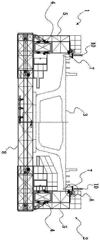
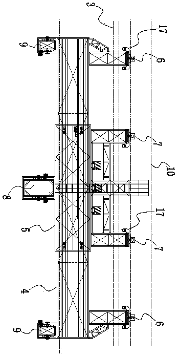
[0051] Example: such as figure 1 and figure 2As shown, the present invention first discloses a bridge detection device comprising left and right two bridge detection mechanisms, the left bridge detection mechanism 1 and the right bridge detection mechanism 2 both include a walking beam body 4 and a socket joint arranged along the length direction of the railway bridge 3 The detection beam body 5 on the walking beam body 4 is provided with a drive mechanism 1 between the walking beam body 4 and the detection beam body 5, and a suspension arm assembly 1 suspended on the railway bridge is provided on the top of the walking beam body 4 6. A suspension arm assembly 2 7 for hanging on the railway bridge is arranged on the top of the detection beam body 5. When any one of the walking beam body 4 and the detection beam body 5 is suspended and fixed on the railway bridge 3 , under the action of the driving mechanism 1, the other beam body can move along the length direction of the ra...


PUM


Abstract

The invention discloses a suspension method for a bridge detection device and suspension arm assemblies. The suspension method includes the steps that when walking beam bodies need to be suspended firstly, the first suspension arm assemblies are controlled to move in the horizontal direction to be inserted in a gap between two adjacent guardrails, the first suspension arm assemblies are then controlled to move downwards in the vertical direction so as to be arranged on the upper surfaces of the bridge edges on the two sides of a railway bridge, then detection beam bodies are controlled to move, after the detection beam bodies move in position, the second suspension arm assemblies are controlled to move in the horizontal direction to be inserted in the gap between the two adjacent guardrails, the second suspension arm assemblies are then controlled to move downwards in the vertical direction so as to be arranged on the upper surfaces of the bridge edges on the two sides of the railway bridge, the first suspension arm assemblies are then controlled to move upwards in the vertical direction, the first suspension arm assemblies are then controlled to move in the horizontal direction to be drawn out of the gap between the two adjacent guardrails, the walking beam bodies are then controlled to move, and suspension actions are conducted alternately in the way till detection operation is finished. By the adoption of the suspension method and the suspension arm assemblies, the bridge detection device can be stably suspended.

Description

technical field [0001] The invention relates to a working method of a bridge detection device and parts of the bridge detection device, in particular to a suspension method and a suspension arm assembly of the bridge detection device. Background technique [0002] my country's high-speed rail passenger dedicated line bridges account for an average of 53% of the line, and the Guangzhou-Zhuhai intercity bridge is as high as 94.2%. Based on the 13,000 kilometers of existing lines, my country's high-speed rail bridges have at least 5,000 kilometers. As the carrier of the high-speed train running track, the bridge must have high ride comfort, high stability and high reliability in order to ensure the safety, stability and ride comfort requirements of the high-speed passenger dedicated line for high-speed operation. Because the traffic accidents caused by bridge hidden dangers are often vicious accidents involving vehicle crashes and fatalities, it is more important and urgent to ...

Claims


Application Information

Patent Timeline
Patent Type & Authority Patents(China)
IPC IPC(8): E01D19/10
CPCE01D19/106
Inventor 罗雀林
Owner 株洲国铁实业有限公司
Why Eureka
Try Eureka