Efficient heat exchange fin

A high-efficiency technology for heat exchange fins, applied to heat sinks, fluid heaters, heat exchange equipment, etc., can solve the problem of uneven distribution of flue gas in fins, improve heat exchange effect, improve heat exchange efficiency, and extend contact the effect of time

Active Publication Date: 2017-05-10
NINGBO FOTILE KITCHEN WARE CO LTD
View PDF9 Cites 6 Cited by
  • Summary
  • Abstract
  • Description
  • Claims
  • Application Information

AI Technical Summary

Problems solved by technology

[0004] The above two patents have improved the existing heat exchange fin structure, but both have the problem of uneven distribution of smoke in the fin, and the heat exchange efficiency needs to be further improved

Method used


Image

  • Efficient heat exchange fin
  • Efficient heat exchange fin
  • Efficient heat exchange fin

Examples


Embodiment Construction

[0020] The present invention will be further described in detail below in conjunction with the accompanying drawings and embodiments.

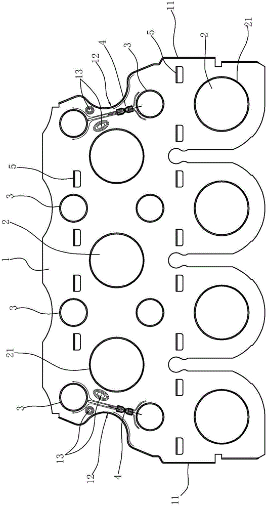
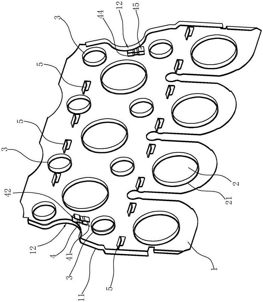
[0021] Such as Figure 1 to Figure 4 As shown, the high-efficiency heat exchange fins include:

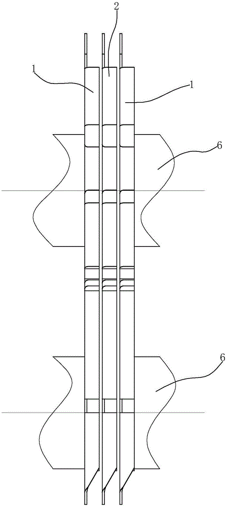
[0022] The base plate 1 is provided with heat exchange tube holes 2 , spoiler rings 3 , guide channels 4 and baffles 5 at intervals on the surface of the base plate 1 .

[0023] in,

[0024] Both sides of the substrate 1 have outwardly protruding flanges 11 , and the flanges located between the upper and lower rows of spoiler coils 3 are recessed inward to form energy-gathering arcs 12 .

[0025] There are multiple heat exchange tube holes 2, which are used to pass through the heat exchange tubes 6. These heat exchange tube holes 2 are arranged alternately in upper and lower rows. There are four heat exchange tube holes 2 in the lower row. There are three heat exchange tube holes 2; protruding flanges 21 are provided along the periphery of the h...


PUM


Abstract

The invention relates to an efficient heat exchange fin. The efficient heat exchange fin comprises a base plate. The surface of the base plate is provided with at least two heat exchange pipe holes at intervals and provided with at least two flow disturbing rings at intervals. The efficient heat exchange fin is characterized in that the heat exchange pipe holes are arranged in two rows, the upper row of heat exchange pipe holes and the lower row of heat exchange pipe holes are staggered, the flow disturbing rings are also arranged in two rows, the upper row of flow disturbing rings and the lower row of flow disturbing rings are staggered, each flow disturbing ring is located above the corresponding heat exchange pipe hole, the two side edges of the base plate are each provided with a turnup protruding outwards, the portion, located between the two rows of flow disturbing rings, of each turnup is recessed inwards, so that an energy gathering arc is formed, the portions, corresponding to the energy gathering arcs, of the surface of the base plate are provided with flow guide channels, the flow guide channels are located between the upper flow disturbing rings and the lower flow disturbing rings, a first end opening of each flow guide channel faces the lower row of flow disturbing rings, and a second end opening of each flow guide channel faces the upper row of flow disturbing rings. The efficient heat exchange fin can greatly improve the heat exchange intensity and the heat exchange efficiency.

Description

technical field [0001] The invention relates to the field of gas water heaters, in particular to a high-efficiency heat exchange fin for a gas water heater. Background technique [0002] CN201420553410.4 discloses a "Heat Exchange Fin for Gas Water Heater", which includes a base plate, on which there are multiple heat exchange tube holes and multiple first flanging holes, and each heat exchange tube hole is The direction runs through the substrate, and the flanges of the plurality of first flanged holes are located on the front side of the substrate, and the first flanged holes are elongated and obliquely arranged on the substrate. According to the heat exchange fin used for the gas water heater of the utility model, the material of the fin used for the gas water heater can be saved and the cost can be reduced. [0003] CN200810196382.4 discloses a "stamped heat exchange fin", which belongs to the technical field of heat exchange facilities. The heat exchanging fins are fo...

Claims


Application Information

Patent Timeline
Patent Type & Authority Applications(China)
IPC IPC(8): F28F1/32F24H9/00
CPCF24H9/0005F28F1/325F28F2215/08
Inventor 王菲徐德明秦刚谭洵茅忠群诸永定周高云
Owner NINGBO FOTILE KITCHEN WARE CO LTD
Why Eureka
Try Eureka