Method, controller and machine for controlling a hydraulic system

A hydraulic system and controller technology, applied in the direction of electric speed/acceleration control, etc., can solve the problem of poor control effect, inability to accurately reflect the engine load state, and the speed load percentage cannot accurately reflect the demand torque and the actual torque everywhere. Differences, etc.

Active Publication Date: 2020-05-26
ZOOMLION HEAVY IND CO LTD
View PDF11 Cites 0 Cited by
  • Summary
  • Abstract
  • Description
  • Claims
  • Application Information

AI Technical Summary

Problems solved by technology

like figure 1 As shown, the interval composed of B and C is the stable time (occurring in the transient process). During the entire interval C, the engine speed line drops sharply, and then quickly recovers. In the area where the engine speed drops rapidly, it is obvious that the required load of the engine is much greater than Output power demand, while the current speed load percentage has been maintained at around 100% at this stage. Obviously, the speed load percentage cannot accurately and truly reflect the difference between the demanded torque and the actual torque everywhere, so it is only based on the current speed load percentage of the engine. The power matching control is bound to fail to achieve the ideal control effect
[0009] Second, in the steady state process, the engine speed cannot accurately reflect the load state of the engine, so the power matching control based on the engine speed ignores the load state and cannot really make the engine work near the load matching point
[0010] like figure 1 As shown, section D is a steady-state process. During the entire section D, the engine speed is consistent with section A (no-load state), and is maintained at a certain value (1000rpm), and the current speed load percentage is determined by the section A. About 20% changes to about 84%. It is obvious that the engine speed in the D range cannot accurately and truly reflect the load of the required engine. Therefore, in the steady state process, the power matching control is only performed according to the engine speed, and the engine cannot be operated accurately. near the load matching point
[0011] Therefore, CN101857175A, CN102021925A and CN102505996A only pay attention to one of the transient state and the steady state process, or expect to adopt a single variable as the feedback amount of the whole strategy in the transient state and steady state process, ignoring the transient state and steady state process. difference, will inevitably lead to poor control effect

Method used


Image

  • Method, controller and machine for controlling a hydraulic system
  • Method, controller and machine for controlling a hydraulic system
  • Method, controller and machine for controlling a hydraulic system

Examples


Embodiment Construction

[0055] Specific embodiments of the present invention will be described in detail below in conjunction with the accompanying drawings. It should be understood that the specific embodiments described here are only used to illustrate and explain the present invention, and are not intended to limit the present invention.

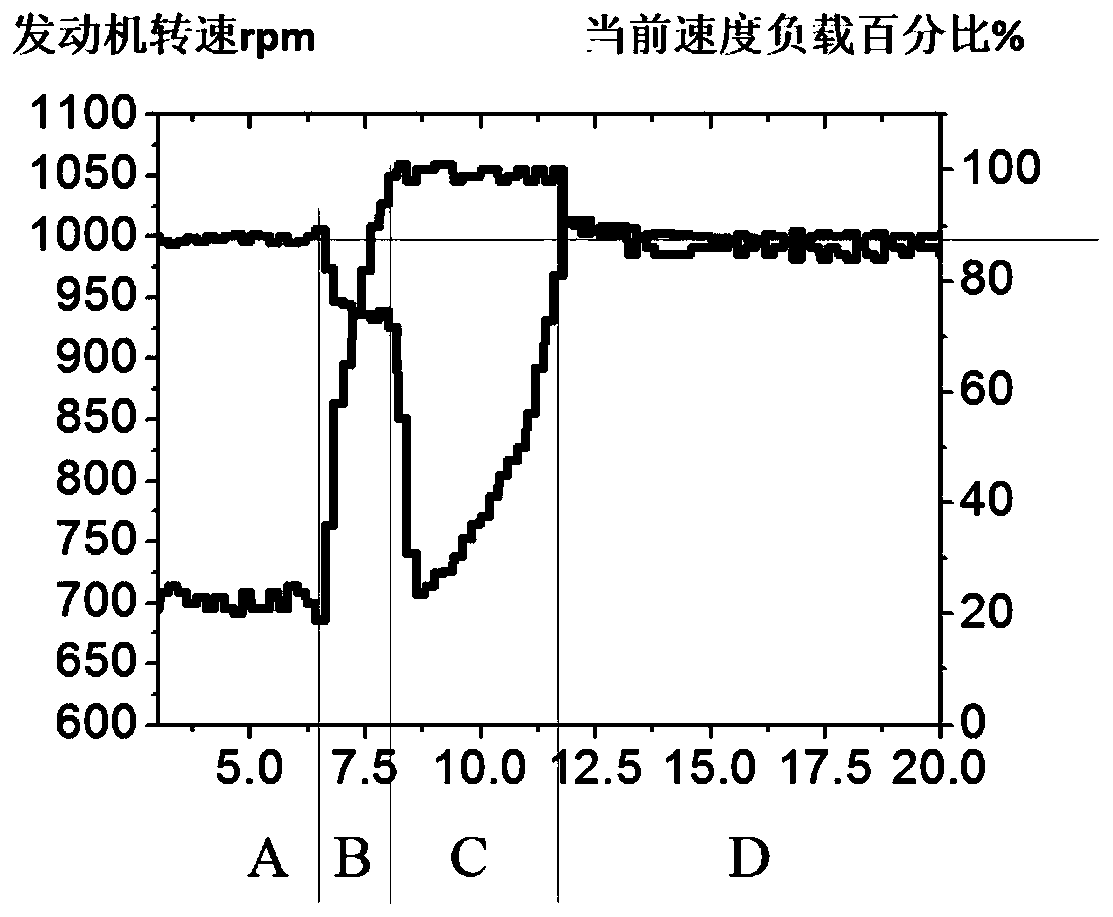
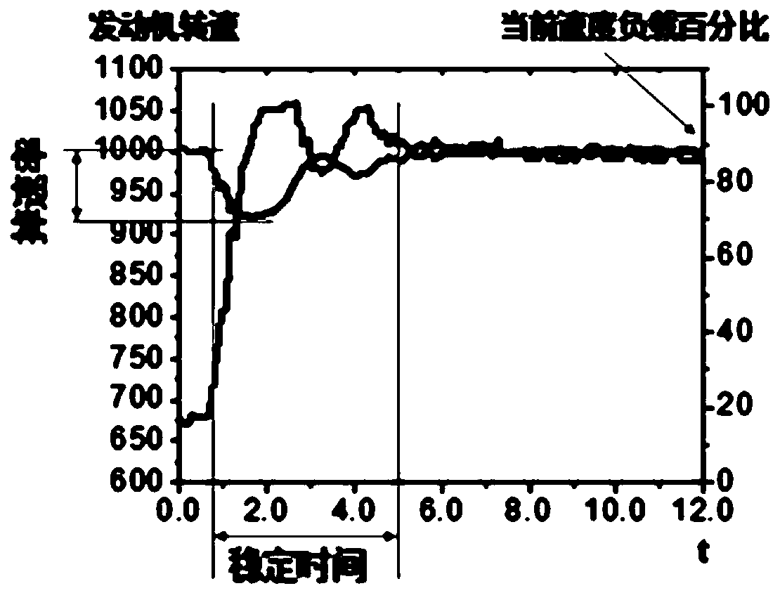
[0056] The term "drop rate" mentioned in this application refers to the percentage of the ratio of the difference between the maximum rotational speed (or minimum rotational speed) of the engine under a sudden load change and the rated rotational speed before the load sudden change to the rated rotational speed.

[0057] The term "current speed load percentage" referred to in this application refers to the ratio of the actual engine torque (indicated torque) to the maximum effective indicated torque at the current engine speed.

[0058] The term "stabilization time" mentioned in this application refers to a period of time from the sudden change of the engine spe...


PUM


Abstract

The application relates to the field of advanced manufacturing equipment and discloses a method and controller for controlling a hydraulic system, and a machine. The method comprises: obtaining engine speed; determining a control mode for controlling the power of the hydraulic system according to the engine speed, wherein the control mode comprises a limit load control mode and a torque matching control mode; determining whether a current control mode is consistent with the determined control mode; if yes, continuing using the current control mode to control the power of the hydraulic system; and if not, performing smooth transition from the current control mode to the determined control mode. The speed and torque compound control method solves engine stall under a limit load condition, and realizes the power matching between the hydraulic system and the engine under a non-limit load condition.

Description

technical field [0001] The invention relates to the field of advanced manufacturing equipment, in particular to a method for controlling a hydraulic system, a controller and a machine. Background technique [0002] When some engineering machinery (such as rotary drilling rigs) are subjected to sudden loads, the engine-hydraulic system power matching control process is divided into the first part of the transient process and the second part of the steady state process. In the first part of the transient process, the engine speed fluctuates. When the sudden load is close to 100% of the rated engine load (called the power limit load condition), the hydraulic pressure is changed by controlling the displacement of the variable main pump or the opening of the hydraulic main valve through the strategy. The required flow rate of the system, and then change the sudden gradient of the engine load to prevent the engine from stalling and black smoke. This process is called limit load co...

Claims


Application Information

Patent Timeline
Patent Type & Authority Patents(China)
IPC IPC(8): G05D13/62
CPCG05D13/62
Inventor 肖承丰袁野王维邹婿邵张劲
Owner ZOOMLION HEAVY IND CO LTD
Why Eureka
Try Eureka