Supercharge Your Innovation With Domain-Expert AI Agents!

Integrated Power Module

A power module and integrated technology, applied in the field of integrated power modules, can solve problems such as complicated process, limited application range, and reduced performance

Active Publication Date: 2019-01-15
IND TECH RES INST
View PDF6 Cites 0 Cited by
  • Summary
  • Abstract
  • Description
  • Claims
  • Application Information

AI Technical Summary

Problems solved by technology

However, this power semiconductor module also does not have an effective fixing mechanism to fix its various components, so it is easy to cause failure due to vibration, and its performance is greatly reduced. In addition, its structural design is too loose to effectively use its internal components. space, making it too bulky and also limiting its scope of application
[0008] Therefore, how to propose an integrated power module that can effectively improve the situation of limited application, complicated process and low performance of the prior art power module has become an urgent problem.

Method used


Image

  • Integrated Power Module
  • Integrated Power Module
  • Integrated Power Module

Examples


Embodiment Construction

[0063] Embodiments of the integrated power module according to the present invention will be described below with reference to related drawings. For ease of understanding, the same components in the following embodiments are described with the same symbols. Besides, the present invention can also be widely implemented in other embodiments. That is to say, the scope of the present invention is not limited by the proposed embodiments, but by the scope of the claims set forth in the present invention.

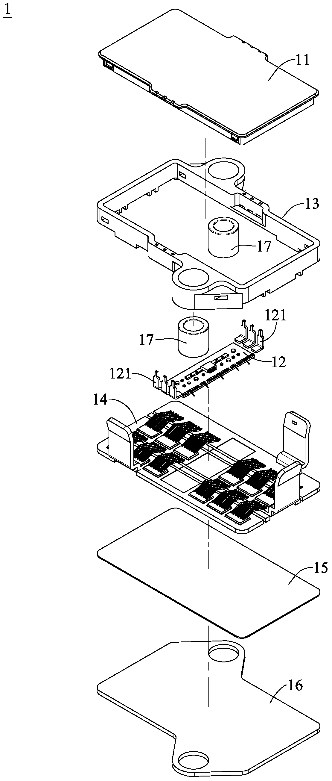
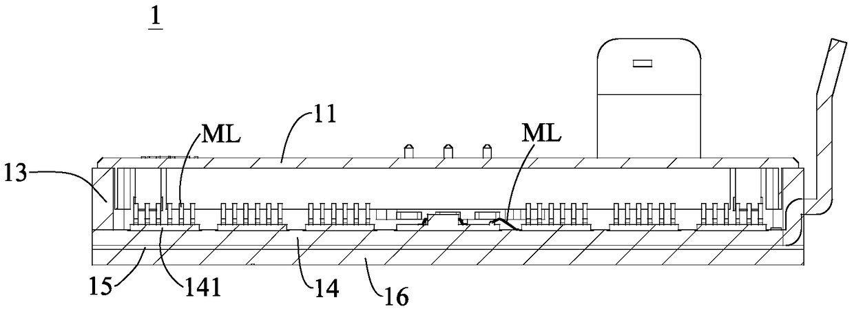
[0064] see figure 1 and figure 2 , which are the first schematic diagram and the second schematic diagram of the first embodiment of the integrated power module of the present invention, figure 1 The exploded view of the integrated power module of this embodiment is illustrated with an example. like figure 1 As shown, the integrated power module 1 may include an upper cover 11 , a gate drive circuit 12 , a ring-shaped outer frame 13 , a power circuit 14 , an insulating heat dis...


PUM


Abstract

An integrated power module may include a gate drive circuit, a plurality of first metal sheets, a plurality of chips, a plurality of second metal sheets and a ring-shaped outer frame. The first metal sheets can be arranged in parallel, and can be electrically connected with the gate driving circuit, and at least one first metal sheet can include a plurality of chip grooves. The chips can be disposed in the chip slots, and each chip can be electrically connected to one of the adjacent first metal sheets. The second metal sheets can be arranged in parallel, and can be electrically connected with the gate driving circuit, and each second metal sheet can be arranged between any two adjacent first metal sheets. The first metal sheets, the second metal sheets, the gate driving circuit and the chips can be arranged in the ring-shaped outer frame.

Description

technical field [0001] The invention relates to a power module, in particular to an integrated power module. Background technique [0002] Generally speaking, the power circuit and the gate drive circuit of the power module in the prior art adopt a separate structure. Therefore, the power circuit and the gate drive circuit need to have their own packaging structures, and the power circuit needs to pass through multiple signal bars. The wire has to be electrically connected to the external gate drive circuit. The above-mentioned structure makes the power module of the prior art too large, so it cannot be applied to light vehicles or small machines. Therefore, the power module of the prior art The scope of application is quite limited. [0003] In addition, because the power module needs to be in a vibrating environment, due to the lack of design, the power module in the prior art cannot effectively fix its components, so the chips of the power circuit and the signal cables b...

Claims


Application Information

Patent Timeline
Patent Type & Authority Patents(China)
IPC IPC(8): H01L25/16H01L23/13H01L23/14
CPCH01L23/13H01L23/14H01L25/16H02M7/003H01L23/367H01L23/42H01L25/162H01L25/165H01L2224/49111H01L2224/49175H05K3/0061
Inventor 简士翔林金亨田庆金宋柏嶒
Owner IND TECH RES INST
Features
  • R&D
  • Intellectual Property
  • Life Sciences
  • Materials
  • Tech Scout
  • Unparalleled Data Quality
  • Higher Quality Content
  • 60% Fewer Hallucinations
Learn More