Wall-suction type router bracket

A router and support frame technology, applied in the direction of selecting devices, electrical components, etc., can solve the problem that the router occupies a large space on the left side and may fall from the support frame, and achieves good stability.

Pending Publication Date: 2017-05-10
MORAL ELECTRICAL APPLIANCE KUNSHAN
View PDF6 Cites 1 Cited by
  • Summary
  • Abstract
  • Description
  • Claims
  • Application Information

AI Technical Summary

Problems solved by technology

[0003] In order to solve the above problems, the invention patent with the patent number of 201520523301.2 discloses a router support, which includes a suction cup, a middle frame, a winding hook, a connecting rod, and a support rod. The middle frame is concave, and the left and right ends of the middle frame are The tops are respectively connected with interlinked suction cups, the two sides of the intermediate frame are respectively provided with circular holes of a certain depth, and each is connected with connecting rods, and the connecting rods are left and right symmetrical, and there are se...

Method used


Image

  • Wall-suction type router bracket
  • Wall-suction type router bracket
  • Wall-suction type router bracket

Examples


Embodiment 1

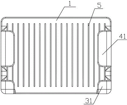
[0022] Such as Figure 1 to Figure 6 The shown wall suction router support includes a support frame body 1, and more than one suction cup 2 is arranged on the back of the support frame body 1 for absorbing the entire bracket on the wall. The preferred number of suction cups 2 in this embodiment There are two, two right angles at the lower end of the support frame body 1 are each provided with a supporting plate 3 for providing upward support to the router, and one is provided on both sides of the front part of the support frame body 1 to prevent the router from moving in the horizontal direction. The moving cross-section is an L-shaped baffle 4; the support frame body 1 is provided with a plurality of cooling grooves 5 running through the front and back.

[0023] The supporting plate 3 described in this embodiment includes a front supporting plate 31 parallel to the support frame body 1, a lower supporting plate 32 connecting the bottom of the supporting frame body 1 and the b...

Embodiment 2

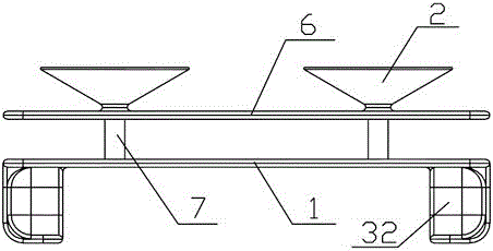
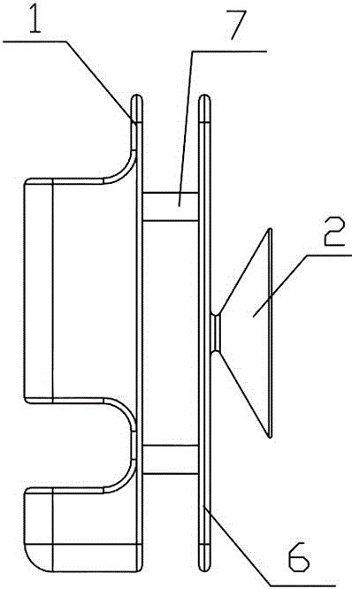
[0026] Compared with Embodiment 1, this embodiment also includes a partition 6, and the back of the partition 6 and the support frame body 1 is connected by a plurality of connecting rods 7, and the preferred number of connecting rods 7 in this embodiment is four , the suction cup 2 is arranged on the partition 6, and the suction cup 2 and the support frame body 1 are respectively located on both sides of the partition 6.

[0027] The preferred number of suction cups 2 in this embodiment is two, the two suction cups 2 are located on the same horizontal straight line, two of the four connecting rods 7 are located above the suction cups, two are located below the suction cups, and four The first connecting rod 7 is located on the four vertices of the same rectangle, and the rest of this embodiment is the same as that of Embodiment 1, and will not be described in detail here.

[0028] Using the router bracket of the present invention, the router bracket is adsorbed to a suitable ...


PUM


Abstract

The invention discloses a wall-suction type router bracket, comprising a support frame body (1), wherein more than one suckers (2) for adsorbing the whole bracket on the wall surface are arranged at the back surface of the support frame body (1), a supporting plate (3) for providing upward support force for the router is respectively arranged at two right angles at the lower end of the support frame body (1), and a baffle (4) which is used for preventing the router from moving in the horizontal direction and is provided with an L-shaped cross section is respectively arranged on two sides of the front part of the support frame body (1). The wall-suction type router bracket disclosed by the invention has the following beneficial effects: according to the router bracket, the router is arranged on the bracket and cannot generate displacement in any direction without applying external force manually, and thus relatively good stability can be achieved; and the router bracket is adsorbed on the wall surface through the sucker, and thus the wall surface cannot be damaged.

Description

technical field [0001] The invention relates to a wall suction router bracket. Background technique [0002] With the development of the Internet era, routers have been widely used in every household, and routers are the hub of the Internet, "traffic police". Nowadays, the use of routers in most families will take up a lot of space on the desktop, destroying people's living environment to a certain extent. [0003] In order to solve the above problems, the invention patent with the patent number of 201520523301.2 discloses a router support, which includes a suction cup, a middle frame, a winding hook, a connecting rod, and a support rod. The middle frame is concave, and the left and right ends of the middle frame are The tops are respectively connected with interlinked suction cups, the two sides of the intermediate frame are respectively provided with circular holes of a certain depth, and each is connected with connecting rods, and the connecting rods are left and right s...

Claims


Application Information

Patent Timeline
IPC IPC(8): H04Q1/04
CPCH04Q1/04
Inventor 王雨池
Owner MORAL ELECTRICAL APPLIANCE KUNSHAN
Why Eureka
Try Eureka