
Electropneumatic control valve

A technology of pneumatic control valve and control valve, which is applied in the direction of brake transmission, control valve, air release valve, brake, etc., can solve the problems of the complexity of the central module and the increase of the power requirements of the central module.

Active Publication Date: 2020-09-04
ZF CV SYST EURO BV
View PDF1 Cites 0 Cited by
  • Summary
  • Abstract
  • Description
  • Claims
  • Application Information

AI Technical Summary

Problems solved by technology

As a result, the complexity of the central module and the power requirements for the central module increase significantly

Method used


Image

  • Electropneumatic control valve

Examples


Embodiment Construction

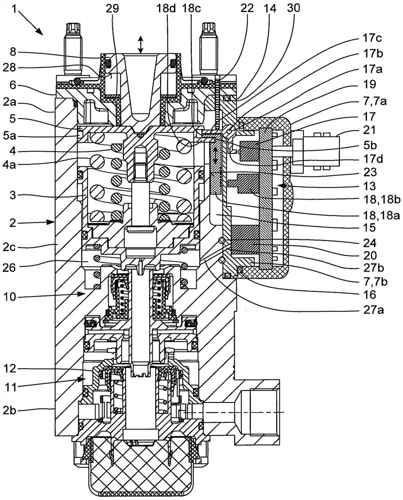
[0021] In the single figure, the electropneumatic control valve according to the invention is designed as an electropneumatic dual circuit brake parameter sensor 1 which is used in the compressed air brake system of a vehicle to regulate the brake pressure in the first and second brake circuit. The brake pressure corresponding to the desired braking effect. Brake parameter detector 1 has a pedal-actuated first valve system 10 arranged in an upper housing region 2 a and a middle housing region 2 c of regulating valve housing 2 , and a lower housing region of regulating valve housing 2 . The second valve system 11 in 2b can be operated pneumatically and / or mechanically by the first valve system 10 .

[0022] In the upper housing region 2 a of the regulating valve housing 2 , the valve piston 3 of the first valve system 10 is axially guided in a sealing manner. Between the valve piston 3 of the first valve system 10 and the circular pressure plate 5 arranged axially above it, a ...


PUM


Abstract

An electropneumatic regulating valve (1), in particular electropneumatic two-circuit braking value transducer in a compressed-air braking system of a vehicle, for the regulated output of a brake pressure, corresponding to a desired braking action, in a first brake circuit and in a second brake circuit, having a first valve system (10) which is arranged in an upper housing region (2a) and in a middle housing region (2c) of a regulating valve housing (2) and which can be actuated by way of a pedal, having a second valve system (11) which is arranged in a lower housing region (2b) of the regulating valve housing (2) and which can be actuated pneumatically and / or mechanically by the first valve system (10), wherein, in the first valve system (10), a valve piston (3) is arranged in the regulating valve housing (2), which valve piston can be displaced axially by means of a plunger piston (8) counter to a spring force, wherein, in a receiving device (14) in the region of the plunger piston (8) or of the valve piston (3) of the first valve system (10), there is arranged an electrical switch (17) for registering the start of actuation of the regulating valve (1) and / or a travel sensor (18) for outputting an electrical travel signal for registering the actuation travel of the plunger piston (8), and wherein the electrical switch (17) and / or the travel sensor (18) are connected to an electronic and / or electromechanical measurement unit (13). In the case of said regulating valve (1), it is provided that the electronic measurement unit (13) is configured as an application-specific sub-unit of an electronically regulated brake system and is arranged in a partially closed electronics housing (7), and that the electronics housing (7) can be exchangeably connected to the receiving device (14).

Description

technical field [0001] The invention relates to an electro-pneumatic regulating valve, especially an electro-pneumatic double-circuit brake parameter detector in a compressed air brake system of a vehicle, which is used to adjust the expected and desired values ​​in the first brake circuit and the second brake circuit. Brake pressure corresponding to the braking action, the electropneumatic regulating valve has a pedal-operated first valve system arranged in the upper and middle housing region of the regulating valve housing, and has a valve system arranged in the regulating valve housing A second valve system in the region of the lower housing which can be actuated pneumatically and / or mechanically via the first valve system, wherein in the first valve system the valve piston is arranged in the regulating valve housing and can be operated by means of the tappet piston Axial displacement against spring force, wherein an electrical switch for registering the start of operation ...

Claims


Application Information

Patent Timeline
Patent Type & Authority Patents(China)
IPC IPC(8): B60T13/66B60T13/68B60T15/02B60T8/17
CPCB60T8/17B60T13/66B60T13/683B60T15/027B60T8/3675B60T13/662B60T15/02B60T2220/04
Inventor 彼得·拜尔乌尔里希·库佩彼得拉·埃尔策亚历山大·法比安斯文·霍曼扬·赫斯特曼格哈德·马蒂尼卡尔-海因茨·里迪格-杰尼施
Owner ZF CV SYST EURO BV
Learn More