
Jewelry box

A jewelry box and jewelry technology, applied in clothing, accessories, applications, etc., can solve problems such as hard to find, hard to find, small space, etc.

Inactive Publication Date: 2017-05-17
CHONGQING IND POLYTECHNIC COLLEGE +1
View PDF4 Cites 13 Cited by
  • Summary
  • Abstract
  • Description
  • Claims
  • Application Information

AI Technical Summary

Problems solved by technology

[0002] Now, jewelry has become an indispensable part of modern women's daily life. With the improvement of living standards, all kinds of jewelry have become indispensable decorations for women, and the use of jewelry boxes has become indispensable. , many people carry jewelry boxes when they go out to store some jewelry to be replaced, so that they can attend different occasions; now there is also a professional stylist, such as going out to take wedding photos or store and sell jewelry, and they carry a lot of jewelry
There are various kinds of jewelry boxes on the market for storing jewelry, including multi-layer foldable and easy-to-carry jewelry boxes, as well as classified multi-layer jewelry boxes. These jewelry boxes are stacked layer by layer, although the space utilization Sufficient, but when taking it, one of the layers is often closed, and then the other layer is opened, or because the space of the box is tightly arranged, it is inconvenient to take things. Many jewelry boxes only have one grid to store many things mixedly. Due to the multi-layer The space is small and difficult to find, such as rings and earrings, which are easy to be mixed in and difficult to find

Method used


Image

  • Jewelry box
  • Jewelry box

Examples


Embodiment Construction

[0017] In order to enable those skilled in the art to better understand, the technical solution of the present invention will be further described below in conjunction with the accompanying drawings and embodiments.

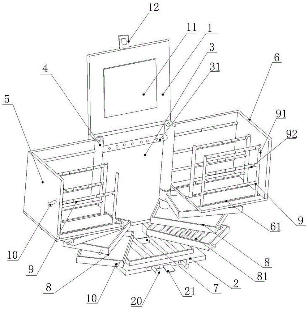
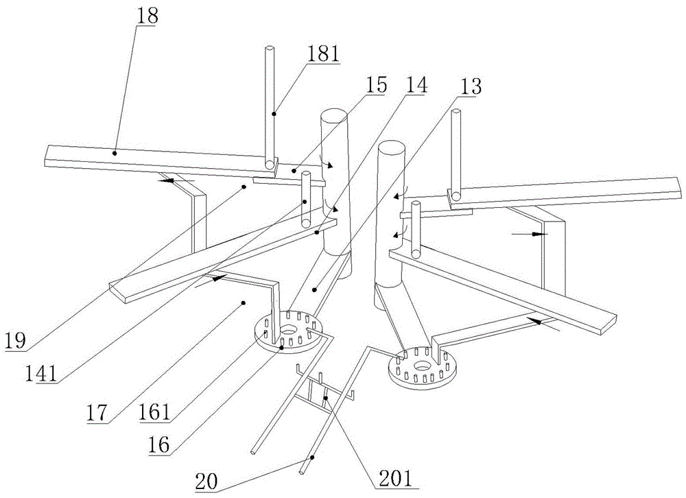
[0018] Such as figure 1 , figure 2 The shown jewelry box comprises a base plate 2, a back plate 3, and a flip cover 1, and the flip cover 1 is hinged on the upper transverse end surface of the back plate 3, and the base plate 2 is fixedly connected perpendicular to the bottom of the back plate 3, at the left and right sides of the back plate 3 Both sides are provided with two vertical central columns 4, and the two central columns 4 are respectively connected with a retractable left-hand rotation mechanism and a right-hand rotation mechanism. 4 The first connecting rod 13, the second connecting rod 14 and the third connecting rod 15 connected by rotation, the first connecting rod 13, the second connecting rod 14 and the third connecting rod 15 are arranged in o...


PUM


Abstract

The invention relates to the field of articles of daily use, and particularly relates to a jewelry box used for holding jewelry. The jewelry box comprises a base plate, a backing plate and an overturning cover, wherein two vertical center poles are arranged on the left side and the right side of the backing plate, and are respectively connected with a left half box and a right half box which are opened by virtue of a left rotating mechanism and a right rotating mechanism; one side of the vertical edge of the left half box and one side of the vertical edge of the right half box are fixed onto the rotating mechanisms by using articulated pieces; storage lattices are arranged on the base plate; through the combination of the rotating mechanisms by virtue of a plurality of connecting rods and rotating discs, storage boxes and the storage lattices on each layer can be exposed out automatically when the storage boxes are rotated and opened towards the two sides, the storage boxes and the storage lattices can rotate at a 15-degree angle by pulling a pull rod in one time when being rotated and opened, so that the layers for storing jewelry are completely exposed out, different types of jewelries are classified and stored, and the jewelry box is beneficial for trimming; besides jewelry, the jewelry box can also used for storing cosmetics; articles inside the left half box, the right half box, the storage boxes, the storage lattices do not interfere with each other when being taken out, and the articles inside the jewelry box are clear at a glance, so that a user can take the jewelry conveniently.

Description

technical field [0001] The invention relates to the field of daily necessities, in particular to a jewelry box for holding jewelry. Background technique [0002] Now, jewelry has become an indispensable part of modern women's daily life. With the improvement of living standards, all kinds of jewelry have become indispensable decorations for women, and the use of jewelry boxes has become indispensable. , Many people carry jewelry boxes when they go out to store some jewelry to be replaced, so that they can attend different occasions; now there is also a professional stylist, such as going out to take wedding photos or store and sell jewelry, and they carry a lot of jewelry. There are various kinds of jewelry boxes on the market for storing jewelry, including multi-layer foldable and easy-to-carry jewelry boxes, as well as classified multi-layer jewelry boxes. These jewelry boxes are stacked layer by layer, although the space utilization Sufficient, but when taking it, one of...

Claims


Application Information

Patent Timeline
IPC IPC(8): A45C11/16A45C13/00A45C13/02
CPCA45C11/16A45C13/00A45C13/02
Inventor 张文
Owner CHONGQING IND POLYTECHNIC COLLEGE
Learn More