An Electric Fixture Loaded in Concealed Tanks of Sea-going Vessels

An electric and fixture technology, applied in the direction of transportation and packaging, load hanging components, etc., can solve the problems of low steel coil loading and unloading quality, coil damage, etc., and achieve the effect of improving quality protection function, high work efficiency, and improving loading utilization space

Active Publication Date: 2018-07-27
SHANGHAI MEISHAN IRON & STEEL CO LTD
View PDF10 Cites 0 Cited by
  • Summary
  • Abstract
  • Description
  • Claims
  • Application Information

AI Technical Summary

Problems solved by technology

The loading and unloading quality of the steel coil is low, which is easy to cause damage to the coil

Method used


Image

  • An Electric Fixture Loaded in Concealed Tanks of Sea-going Vessels
  • An Electric Fixture Loaded in Concealed Tanks of Sea-going Vessels
  • An Electric Fixture Loaded in Concealed Tanks of Sea-going Vessels

Examples


Embodiment 1

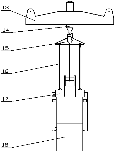
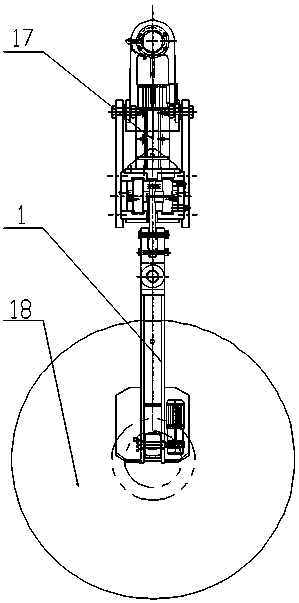
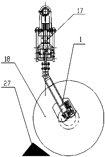
[0020] see figure 1 , figure 2 , image 3 , an electric clamp loaded in a concealed cabin of a seagoing ship, the electric clamp includes a loading and unloading bridge balance beam 13, a main hook 14, a triangular balance beam 15, a steel wire rope 16 and an electric clamp body 17, and the main hook 14 is arranged on the loading and unloading bridge balance beam 13 and the triangular balance beam 15, the steel wire rope 16 is arranged between the triangular balance beam 15 and the electric clamp body 17; the electric clamp body 17 includes the lifting lug 4 and the clamp beam, and a guide plate box is arranged above the clamp beam 2. The distribution box 5 and the transmission device 3, the swinging pincer legs 1 are arranged symmetrically on both sides of the fixture beam, and the double hook lifting lugs 6 are also arranged on the fixture beam. The technical solution ensures the personal safety of the conductor in the cabin, and even if there is a collision with other st...

Embodiment 2

[0022] see figure 1 , image 3 , as an improvement of the present invention, the electric clamp body also includes a swing leg intermediate joint 7 and a main hanging plate 8, and the swing tong leg 1 is arranged on the double hook lifting lug through the swing leg intermediate joint 7 and the main hanging plate 8 6 on. The rest of the structures and advantages are exactly the same as in Embodiment 1.

Embodiment 3

[0024] see figure 1 , image 3 , Figure 4 , Pic 4-1 , Figure 4-2 , as an improvement of the present invention, the swing pliers 1 and the swing leg intermediate joint 7 are connected through a damping adjustment component; the damping adjustment component includes a fixed adjustment disc 9, a rotating shaft 10, a damping adjustment screw 11, a damping friction Sheet 12, the damping friction sheet 12 is fixed on the side of the swing leg middle joint 7, refer to Figure 4-2 It is a schematic diagram of the structure of the swing intermediate joint. The fixed adjusting disc 9 is provided with a slot to fix the rotating shaft 10. The fixed adjusting disc 9 and the swinging pliers leg 1 are fixed together by four damping adjusting screws 11 with a diameter of 20 mm. Controllable damping can be realized by rotating 4 adjusting screws in both directions, and by adjusting the pressure between the screw and the damping friction plate. fixed. This arrangement is simple in stru...


PUM


Abstract

The invention relates to an electric clamp loaded on seagoing vessel hidden cabin. The electric clamp comprises a loading bridge equalizer bar, a main hook, a triangle equalizer bar, a wire rope and an electric clamp main body, the main hook is arranged between the loading bridge equalizer bar and the triangle equalizer bar, and the wire rope is arranged between the triangle equalizer bar and the electric clamp. When the hidden cabin works, a front leg of the clamp swings with a certain angle, the 1.5 m of the hidden cabin at the left and right sides of the seagoing vessel loaded with cargo can be effectively used, the clamp sends the cargo to the hidden cabin, a clamp feet of the clamp is contracted into the front leg, and the function of swing of the front leg is realized under gravity effect. The cargo compartment is effectively used, the quality of the loaded cargo is protected, and the loading efficiency is guaranteed.

Description

technical field [0001] The invention relates to an electric clamp, in particular to an electric clamp loaded in a concealed cabin of a sea-going vessel, and belongs to the technical field of highly integrated electromechanical clamp equipment for wharves. Background technique [0002] The concealed loading of ocean-going vessels involves spreaders transported by ports, and a specific loading and unloading method is used to solve the hidden-tank loading operations of ocean-going vessels by using highly integrated electromechanical fixtures at the wharf. Hidden warehouse refers to a small space recessed inside the two sides of a seagoing ship, and the bottom has an inclined angle. Because the deck plane of the seagoing ship is relatively protruding, the balance beam and hooks in the vertical state cannot touch the concealed cabin, and must be moved there by other means. When seagoing ships are loading and unloading cargo at the port, especially when loading and unloading brid...

Claims


Application Information

Patent Timeline
Patent Type & Authority Patents(China)
IPC IPC(8): B66C1/00
Inventor 王益祥杨浩李平吕爱林朱惠华王林詹红
Owner SHANGHAI MEISHAN IRON & STEEL CO LTD
Why Eureka
Try Eureka