Pressure status or switch status indicator

A switch status and indicator technology, applied in the direction of measuring fluid pressure, piston type fluid pressure measurement, measuring fluid pressure through mechanical components, etc.

Active Publication Date: 2019-07-16
BAYERISCHE MOTOREN WERKE AG
View PDF5 Cites 0 Cited by
  • Summary
  • Abstract
  • Description
  • Claims
  • Application Information

AI Technical Summary

Problems solved by technology

Otherwise there is a considerable health risk during rescue

Method used


Image

  • Pressure status or switch status indicator
  • Pressure status or switch status indicator
  • Pressure status or switch status indicator

Examples


Embodiment Construction

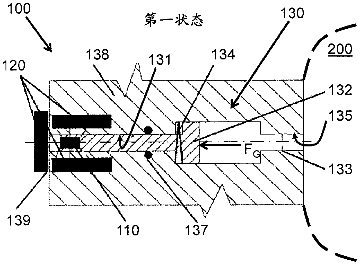
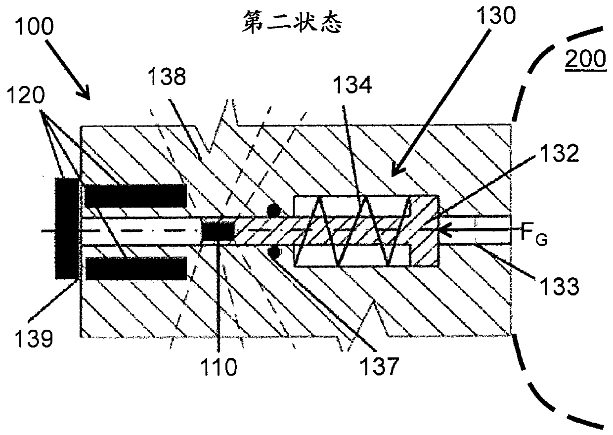
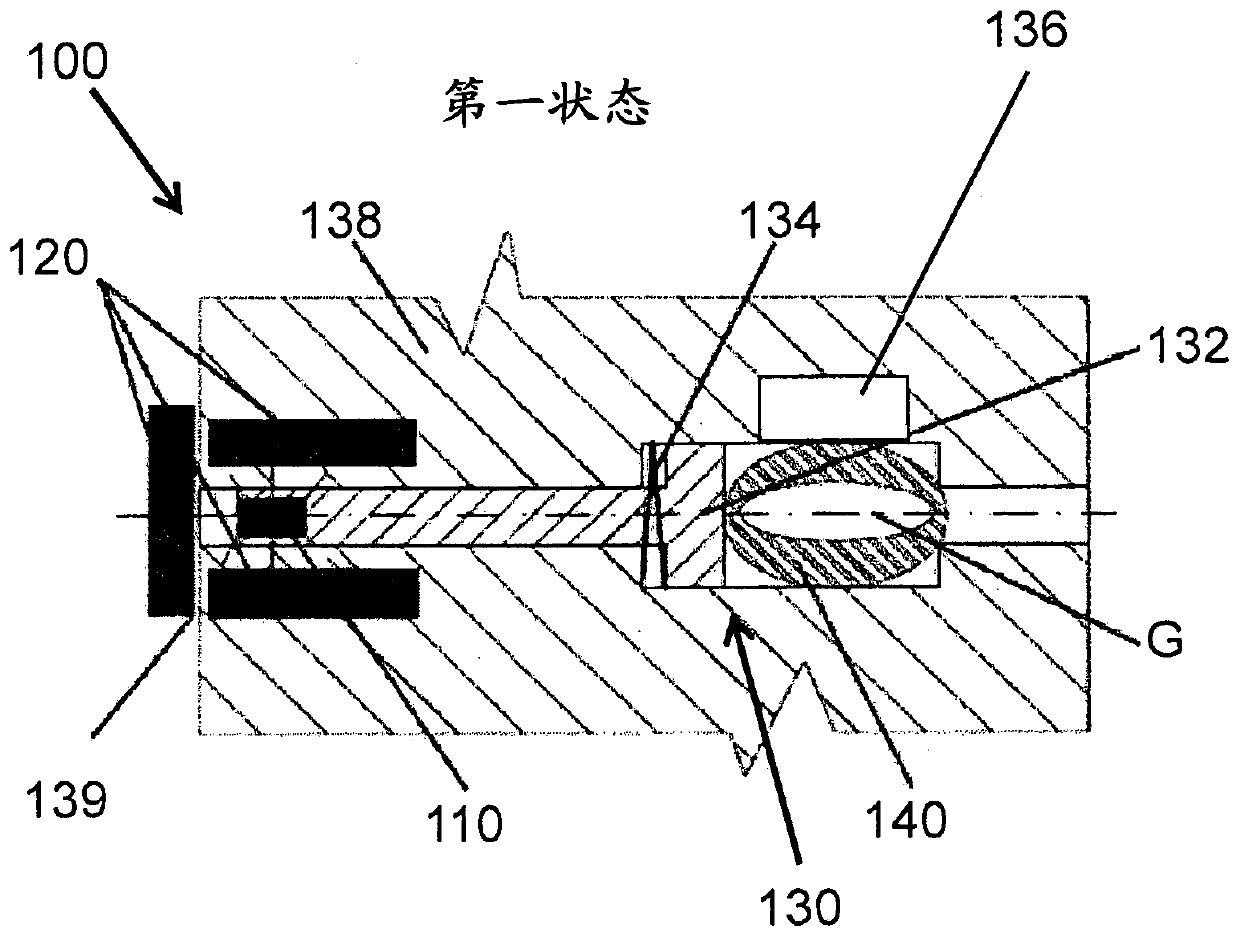
[0047] figure 1 The shown indicator is a pressure state indicator 100 and includes a radiation source 110 which is housed here in a radiation protection device 120 . The radiation protection device 120 here comprises a lead shield made of a lead plate 120 which absorbs the radiation continuously emitted by the radiation source 110 . Due to this shielding, no radiation escapes from the radiation protection device 120 . The radiation source 110 is fixed on the piston rod of the piston 132 . A piston 132 is guided in a piston well 131 of a housing 138 . Housing 138 also includes a fluid passage 135 that communicates piston 132 at least indirectly with the interior of the pressure vessel. For example, the pressure state indicator 100 can be connected with the pressure vessel 200 through the on-tank-ventil of the tank (in figure 1 and 2 The pressure vessel 200 is only schematically shown in dashed lines). One side of the piston 132 is loaded with a spring force by a spring 13...


PUM


Abstract

The invention relates to a display (100) comprising: a radiation source (110) which can emit radiation; radiation protection (120) which is designed to shield the radiation source; and an actuator (130) which can transfer the display from a first state into a second state. In the first state, the radiation source shields the emitted radiation and in the second state, at least one part of the emitted radiation is not shielded.

Description

technical field [0001] The technology disclosed herein relates to a pressure state or switch state indicator. Background technique [0002] Pressure vessels or pressure tanks are known from the prior art. The pressure vessel is, for example, a high-pressure gas vessel or a cryogenic pressure vessel. Composite pressure vessels are also commonly referred to as composite vessels or fiber composite vessels. Type II, Type III and Type IV pressure vessels have fully or partially a layer of fiber reinforcement surrounding the (inner) liner. Fiber-reinforced plastics (FVK) are used, for example, carbon-fiber-reinforced plastics (CFK) and glass-fiber-reinforced plastics (GFK). Liners are made of metal (usually aluminum or steel) in Type II and Type III vessels. Pressure vessels hold compressed fluids such as compressed air, oxygen, methane, hydrogen, carbon dioxide, etc. Furthermore, plastic liners are known (all-composite containers, Type IV containers). High-pressure gas cont...

Claims


Application Information

Patent Timeline
Patent Type & Authority Patents(China)
IPC IPC(8): G01L7/16G01L19/10
CPCB60R21/00B60R2021/0027F17C2205/0332G01L7/166G01L19/10
Inventor J-M·孔贝格尔
Owner BAYERISCHE MOTOREN WERKE AG
Why Eureka
Try Eureka