Hydraulic jack upper cover sealing structure

A technology of hydraulic jack and sealing structure, applied in the direction of lifting device, etc., can solve the problems of easy wear of the sealing ring, deflection of the piston rod moving up and down, dust entering, etc., and achieve the effect of preventing wear of the sealing ring and good guiding effect.

Inactive Publication Date: 2017-05-24
衡阳市锦泰工具有限公司
View PDF3 Cites 0 Cited by
  • Summary
  • Abstract
  • Description
  • Claims
  • Application Information

AI Technical Summary

Problems solved by technology

It solves the problem that the sealing ring between the top cap and the piston rod of the existing hydraulic jack is easy to wear, causing dust to enter the gap between the piston rod and the oil cy

Method used


Image

  • Hydraulic jack upper cover sealing structure
  • Hydraulic jack upper cover sealing structure
  • Hydraulic jack upper cover sealing structure

Examples


Embodiment 1

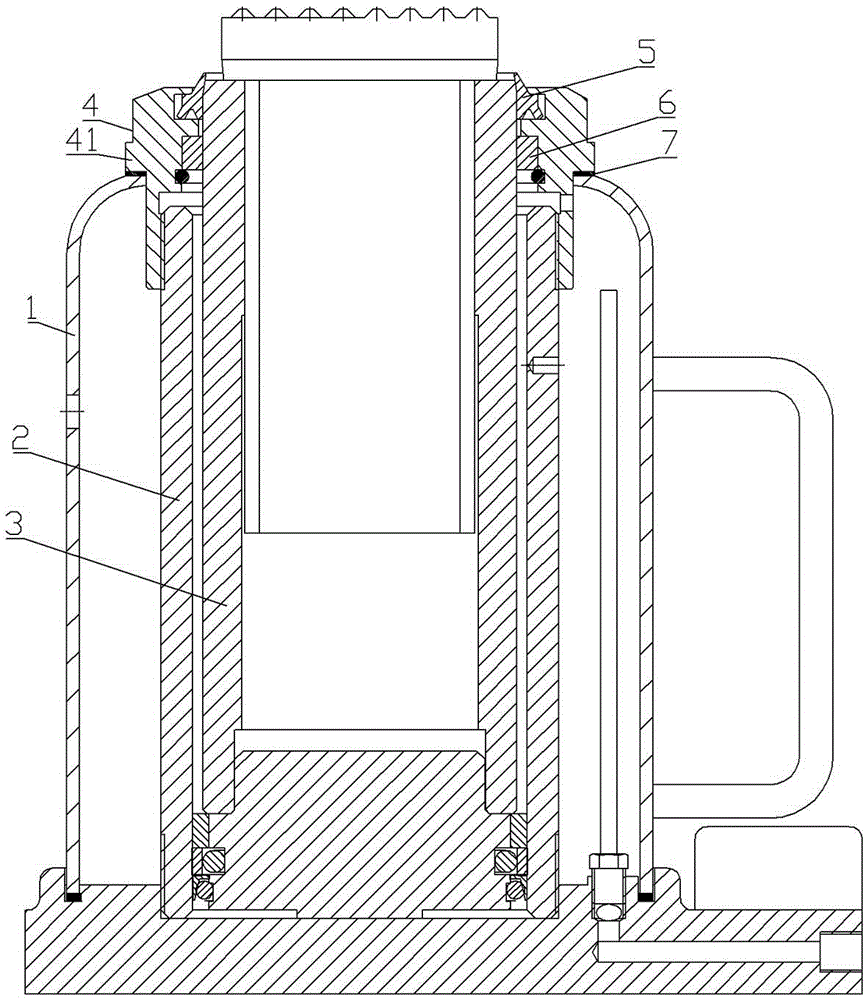
[0016] The sealing structure of the upper cover of the hydraulic jack includes a casing 1, an oil cylinder 2, a piston rod 3 and a top cap 4.

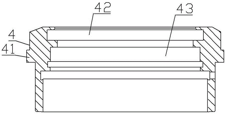
[0017] Oil cylinder 2 is arranged in shell 1. Piston rod 3 is arranged in oil cylinder 2, and its upper end stretches out from oil cylinder 2 and is positioned at top cap 4 upper end inner hole. The top cap 4 is in the shape of a sleeve with openings at both ends, and its outer edge is provided with an annular boss 41, which is threaded on the outer edge of the upper end of the oil cylinder 2 through the internal thread in the inner hole of the lower end. The groove A42 and the groove B43 are provided in sequence, and the lower annular surface of the annular boss 41 is against the shell 1 to provide positioning for the shell 1;

[0018] A dustproof ring 5 and a guide sleeve 6 are arranged between the top cap 4 and the piston rod 3 . The dustproof ring 5 is installed in the groove A42, and the guide sleeve 6 is installed in the groove...


PUM


Abstract

The invention discloses a hydraulic jack upper cover sealing structure. The hydraulic jack upper cover sealing structure comprises an outer shell, an oil cylinder, a piston rod and a top cap. The oil cylinder is arranged in the outer shell. The piston rod is arranged in the oil cylinder, and the upper end of the piston rod extends out of the oil cylinder and is located in an inner hole in the upper end of the top cap. The top cap is in a sleeve shape with the two ends opened. An annular boss is arranged at the outer edge of the top cap. The top cap is in threaded connection to the outer edge of the upper end of the oil cylinder through an internal thread in an inner hole in the lower end of the top cap. The lower annular face of the annular boss of the top cap abuts against the outer shell, so that the outer shell is located. The hydraulic jack upper cover sealing structure is characterized in that a dustproof ring and a guiding sleeve are arranged between the top cap and the piston rod.

Description

technical field [0001] The invention relates to a sealing structure of a hydraulic jack, in particular to a sealing structure of an upper cover of a hydraulic jack. Background technique [0002] The hydraulic jack is a common lifting device in industrial production, and the sealing performance of its sealing parts is the key to whether the hydraulic jack can work normally. Its jacking and unloading are accomplished by the piston moving up and down in the inner wall of the cylinder. [0003] The upper end of the hydraulic jack is sealed by a top cap, and the top cap is threaded on the outer edge of the upper end of the cylinder through the inner thread of the lower section of the inner hole. . At present, there is only a sealing ring between the upper part of the inner hole of the top cap and the outer edge of the piston rod in the existing hydraulic jack. In the gap between the piston rod and the oil cylinder, and the piston rod is easily deflected due to lack of guidance...

Claims


Application Information

Patent Timeline
IPC IPC(8): B66F3/25B66F3/24
CPCB66F3/25B66F3/24B66F2700/05
Inventor 陈声亮刘亚洲邓悦
Owner 衡阳市锦泰工具有限公司
Why Eureka
Try Eureka