No-secondary light spot LED reflector

A reflector and sub-spot technology, which is applied in the field of reflectors, can solve the problems of uneven brightness in the illumination area, waste of light source illumination, and easy to cause myopia, etc., and achieve the effects of avoiding uneven illumination, good guidance, and good brightness

Pending Publication Date: 2018-10-16
中山雅大光电有限公司
View PDF0 Cites 0 Cited by
  • Summary
  • Abstract
  • Description
  • Claims
  • Application Information

AI Technical Summary

Problems solved by technology

[0005] There is uneven brightness in the illuminated area. Uneven illumination leads to waste of light source illumination. At the same t

Method used


Image

  • No-secondary light spot LED reflector
  • No-secondary light spot LED reflector
  • No-secondary light spot LED reflector

Examples


Embodiment 1

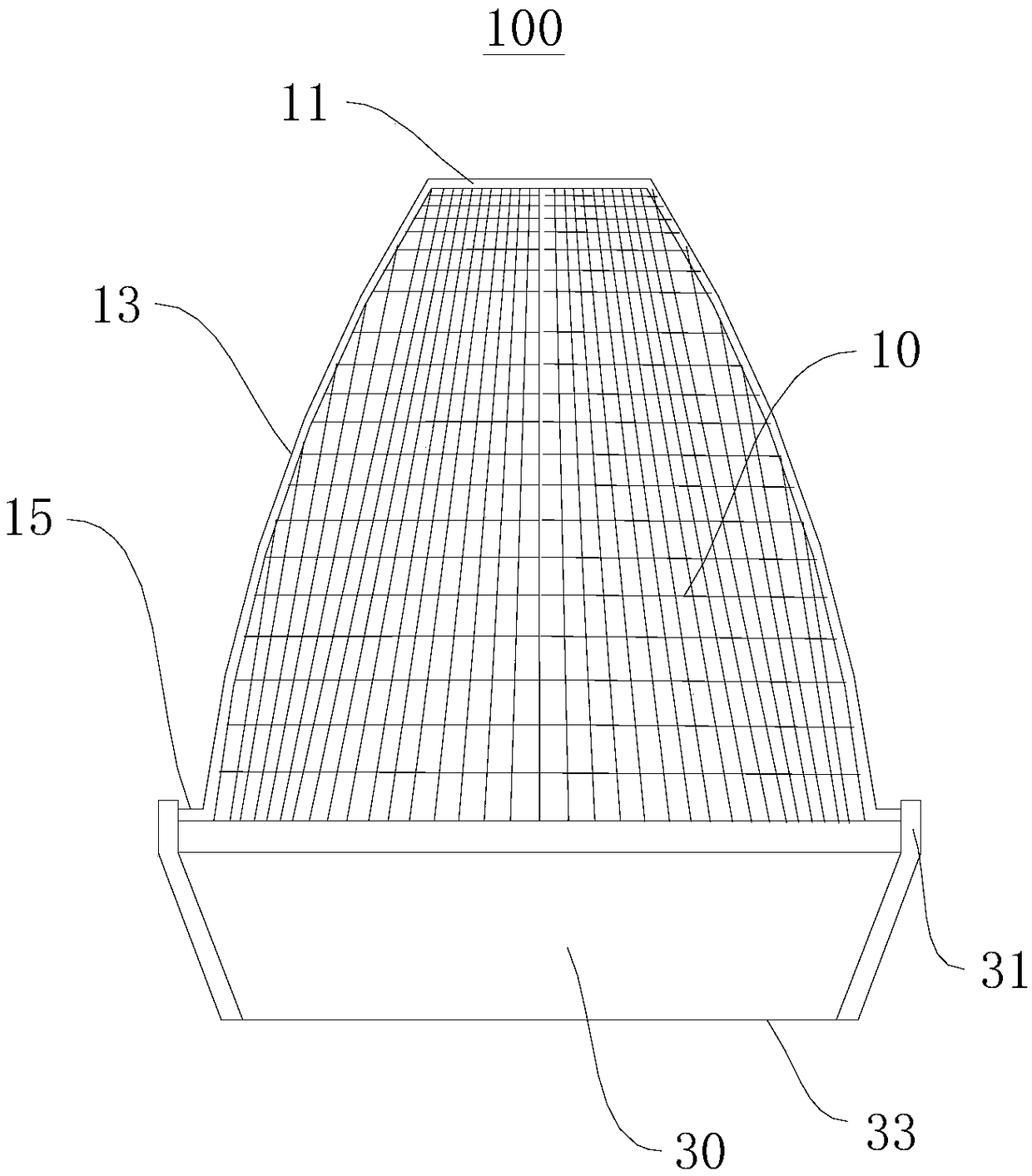
[0040] Please refer to Figure 1 to Figure 3 , this embodiment provides an LED reflector 100 without secondary facula, including:

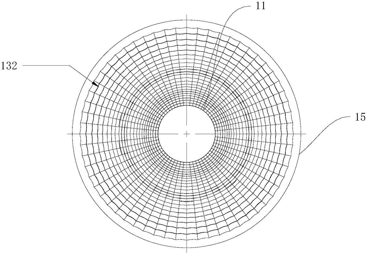
[0041] A reflector 10, the reflector 10 includes a cover head 11, a cover body 13 and a cover platform 15, the cover head 11 and the cover platform 15 are respectively located at the two ends of the cover body 13, the cover head 11 is used to cover the LED lamp beads, the reflector 10 The size of the cross-sectional profile gradually increases from the side of the cover head 11 to the side of the cover platform 15;

[0042] A light receiving ring 30, the light receiving ring 30 includes a connecting portion 31 and a light receiving port 33, the connecting portion 31 is connected to the cover platform 15, and the cross-sectional profile size of the light receiving ring 30 gradually decreases from the connecting portion 31 to the light receiving port 33;

[0043] The light emitted by the LED lamp bead can be projected from the cover head 11 toward ...

Embodiment 2

[0062] This embodiment also provides an LED reflector 100 without secondary facula. The main differences between this embodiment and Embodiment 1 are:

[0063] The diameter of the outer circle of the cover table 15 is 68 mm, the diameter of the inner circle of the cover head 11 is 18.3 mm, and the height of the reflector 10 is 60.2 mm;

[0064] Correspondingly, the diameter of the inner circle of the connecting portion 31 is 68 mm, the diameter of the inner circle of the light receiving port 33 is 57.6 mm, and the height of the portion between the connecting portion 31 and the light receiving port 33 is 29.5 mm.

[0065] All the other structures can refer to embodiment 1.

[0066] Such dimensional design can also achieve the technical effect in Embodiment 1.

Embodiment 3

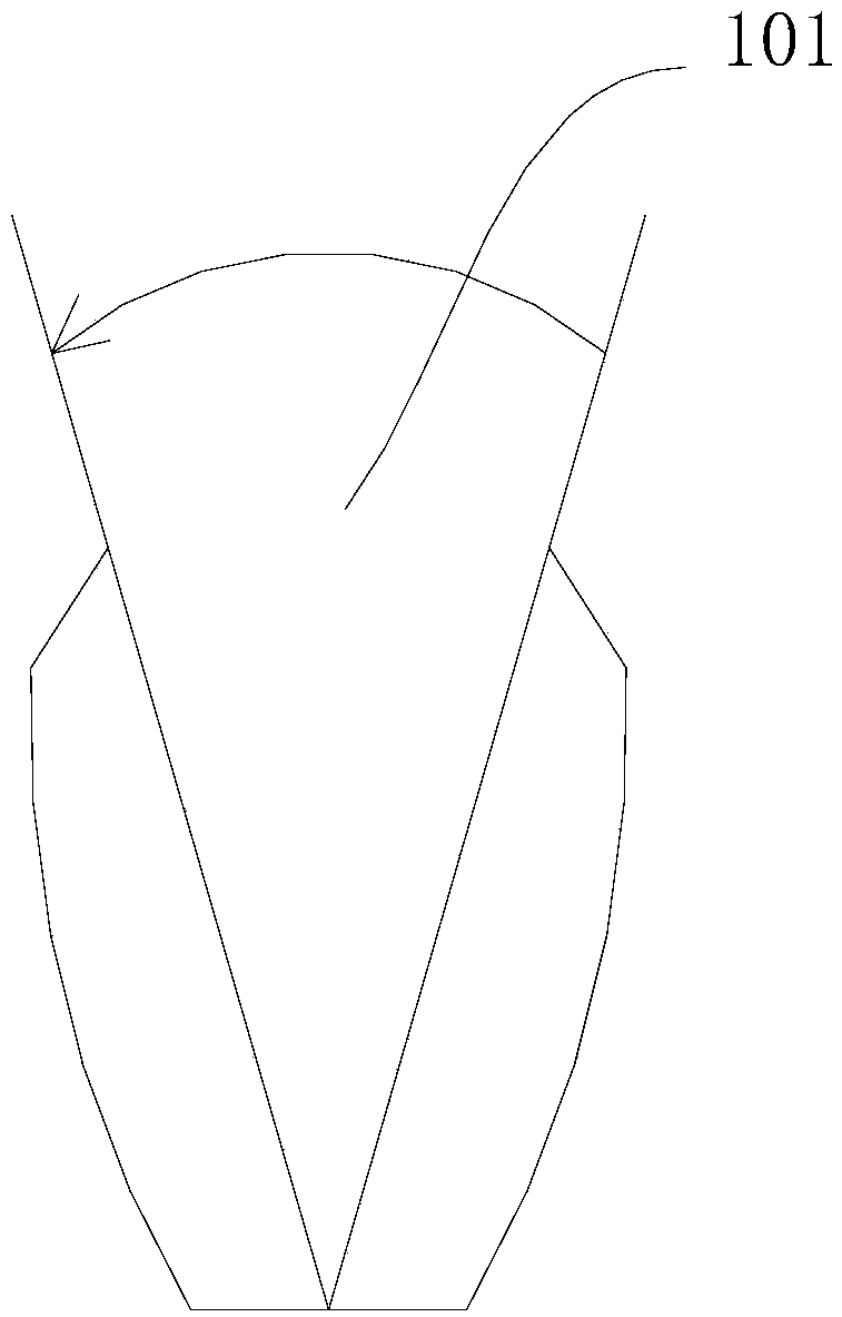
[0068] Please refer to Figure 4 , this embodiment provides a LED reflector 100 without secondary facula, the main difference between this embodiment and Embodiment 1 is:

[0069] The cover body 13 includes a first part 134 and a second part 136, the first part 134 is close to the cover head 11, the second part 136 is close to the cover platform 15, and the cut surface of the inner surface of the cover body 13 is outside the first part 134. The cut surface is an inner cut surface at the second part 136 , and the outer cut surface and the inner cut surface transition at the junction of the first part 134 and the second part 136 .

[0070] All the other structures can refer to embodiment 1.

[0071] Through the design of the cover body 13, the light emitted by the light source has the effect of converging towards the center when the first part 134 is in place. With the structure of the light receiving ring 30, it can also prevent the occurrence of secondary light spots like Emb...


PUM

PropertyMeasurementUnit
Diameteraaaaaaaaaa
Diameteraaaaaaaaaa
Heightaaaaaaaaaa

Abstract

The invention provides a no-secondary light spot LED reflector, and relates to the technical field of reflectors. The no-secondary light spot LED reflector comprises a reflecting cover and a light collecting ring, wherein the reflecting cover comprises a cover head, a cover body and a cover table; the cover head and the cover table are respectively positioned at two ends of the cover body; the cover head is used for covering LED beads; and the section profile size of the reflecting cover is gradually increased from one side of the cover head to one side of the cover table. The light collectingring comprises a connecting part and a light collecting port; the connecting part is connected with the cover table; and the section profile size of the light collecting ring is gradually reduced from the connecting part to the light collecting port. Light emitted by the LED beads can be projected from the cover head to the light collecting port and outwards emitted from the light collecting port. The no-secondary light spot LED reflector can prevent generation of secondary light spots during illuminating, so that the illumination is more uniform, and the problems caused by nonuniform illumination are prevented.

Description

technical field [0001] The invention relates to the technical field of reflectors, in particular to an LED reflector without secondary light spots. Background technique [0002] LED lamp lighting components have the characteristics of energy saving, long service life, stable light intensity, etc., and more and more commercial and civilian applications have been promoted and applied. At the same time, although the LED lamp has a bright projection light distance, its projection effect is in a straight line, and the illumination range is limited. [0003] In order to solve the above-mentioned limitations of LED lamps, reflectors or reflectors are generally used to reflect the projected light of LED lamps to form diffused light to improve the lighting range and light comfort. [0004] But there are still some problems with reflector: [0005] There is uneven brightness in the illuminated area. Uneven illumination leads to waste of light source illumination. At the same time, f...

Claims


Application Information

Patent Timeline
IPC IPC(8): F21V7/04F21V7/28
CPCF21V7/04F21V7/22
Inventor 邱磊江景芳
Owner 中山雅大光电有限公司
Why Eureka
Try Eureka