Bladeless fan

A bladeless fan and air ring technology, which is applied to non-variable pumps, pump components, and parts of pumping devices for elastic fluids, can solve the problem of affecting the smoothness of the air intake, occupying a large space, and increasing the useless Improve the smoothness of the air intake and improve the efficiency of the air supply

Inactive Publication Date: 2017-05-24
GREE ELECTRIC APPLIANCES INC OF ZHUHAI
View PDF0 Cites 5 Cited by
  • Summary
  • Abstract
  • Description
  • Claims
  • Application Information

AI Technical Summary

Problems solved by technology

[0003] For existing bladeless fans, if the air outlet direction is the front and rear direction, the air inlet is usually arranged on the left or right surface of the casing, so that the air inlet direction is perpendicular to the air outlet direction, which affects the smoothness of the air inlet , it is also easy to increase the thickness of the bladeless fan in the air outlet direction, resulting in a larger volume of the bladeless fan and a larger space occupied

Method used


Image

  • Bladeless fan
  • Bladeless fan
  • Bladeless fan

Examples


Embodiment Construction

[0032] The following will clearly and completely describe the technical solutions in the embodiments of the present invention with reference to the accompanying drawings in the embodiments of the present invention. Obviously, the described embodiments are only some, not all, embodiments of the present invention. The following description of at least one exemplary embodiment is merely illustrative in nature and in no way taken as any limitation of the invention, its application or uses. Based on the embodiments of the present invention, all other embodiments obtained by persons of ordinary skill in the art without creative work fall within the protection scope of the present invention.

[0033] Techniques, methods and devices known to those of ordinary skill in the relevant art may not be discussed in detail, but where appropriate, such techniques, methods and devices should be considered part of the Authorized Specification.

[0034] In the description of the present invention...


PUM

PropertyMeasurementUnit
Gap sizeaaaaaaaaaa

Abstract

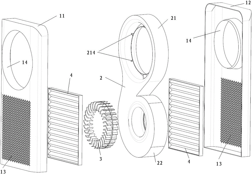
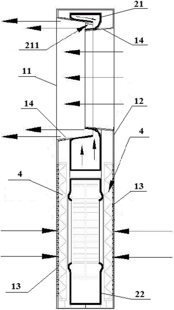
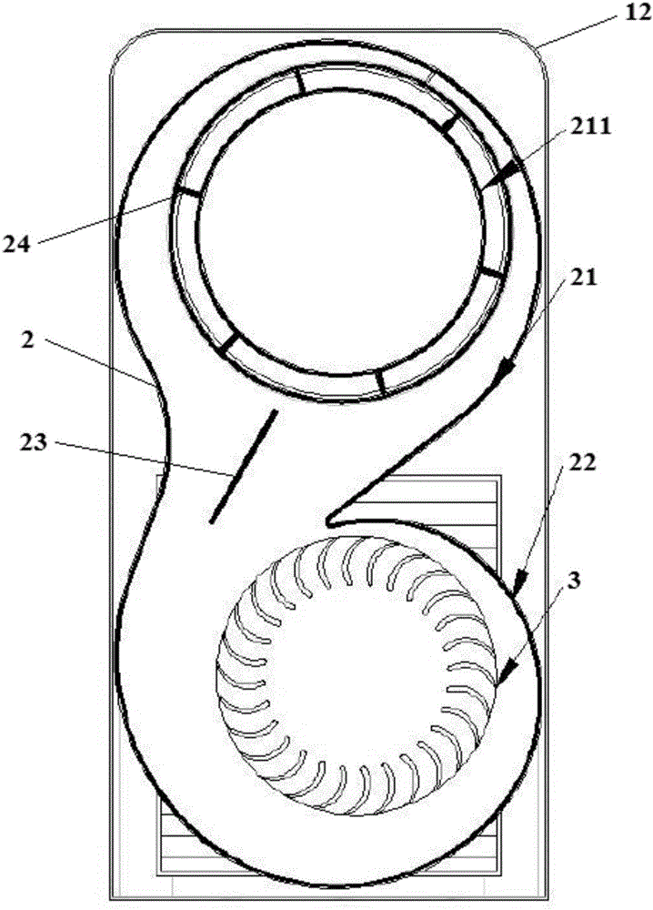
The invention relates to the technical field of fans, in particular to a bladeless fan. The bladeless fan provided by the invention comprises a shell, a wind duct structure, a wind inlet formed in the shell, and a wind wheel arranged in the shell. The wind duct structure comprises a wind ring portion with an annular wind outlet gap, and air is driven by the wind wheel to enter the wind duct structure from the wind inlet and flow out from the annular wind outlet gap. The bladeless fan is characterized in that the wind inlet and the wind ring portion are arranged on the shell in the mode that the central axis of the wind inlet is roughly perpendicular to the central axis of the wind ring portion, so that the wind inlet direction is roughly parallel to the air outlet direction; and the air inlet direction refers to the direction in which air enters into the shell from the wind inlet, and the air outlet direction refers to the direction in which air flows out from the annular wind outlet gap. Since the wind inlet direction is roughly parallel to the air outlet direction, the wind inlet smoothness of the bladeless fan can be improved, and the wind feeding efficiency of the bladeless fan is improved.

Description

technical field [0001] The invention relates to the technical field of fans, in particular to a bladeless fan. Background technique [0002] The bladeless fan is also called air doubling machine, which uses the impeller to inhale air from the air inlet at the bottom and drive the air to flow out from the annular air outlet gap on the wind ring part. The air flowing out from the annular air outlet gap can entrain the wind ring The air at the end flows forward together, amplifying the airflow, and finally forming a natural and continuous cool breeze. Compared with the bladed fan, the bladeless fan has no exposed fan blades, so not only can the problem of dust accumulation on the fan blades be effectively avoided, but also it is safer to use. [0003] For existing bladeless fans, if the air outlet direction is the front and rear direction, the air inlet is usually arranged on the left or right surface of the casing, so that the air inlet direction is perpendicular to the air o...

Claims


Application Information

Patent Timeline
IPC IPC(8): F04D25/08F04D29/28F04D29/42F04D29/44F04D29/70
CPCF04D25/08F04D29/282F04D29/4226F04D29/4233F04D29/441F04D29/703
Inventor 尚勇李曙光陈宇强柳州贾铌梁浩闫鲁华
Owner GREE ELECTRIC APPLIANCES INC OF ZHUHAI
Why Eureka
Try Eureka