Cutting test device

A technology of cutting test and pick, which is applied in the field of cutting test, can solve problems such as the inability to effectively study the matching of pick installation parameters, and achieve the effect of improving operation performance

Pending Publication Date: 2017-05-24
JIANGSU XCMG CONSTR MASCH RES INST LTD +1
0 Cites 3 Cited by

AI-Extracted Technical Summary

Problems solved by technology

[0005] A technical problem to be solved by the present invention is: in the existing cutting test device, the pick installation parameters a...

Method used

Because different coal rocks have less influence on the pick chamfer, that is, when cutting different coal rocks, the pick can be installed with approximately equal chamfers, therefore, the angle adjustment mechanism 2 of the present invention is preferably It is set to be able to adjust the rotation angle of the pick 11 and/or the elevation angle of the pick 11 without adjusting the chamfer of the pick 11, so as to provide more accurate data support for the matching of the installation parameters of the pick 11 and the characteristics of different coal rocks , and can effectively simplify the structure of the cutting test device and reduce the cost of the cutting test device. Wherein, in order to realize the adjustment to the angle of rotation of the pick 11, the angle adjustment mechanism 2 of the present invention may include a rotation angle adjustment mechanism for adjusting the angle of rotation of the pick 11; in order to realize the adjustment of the elevation angle of the pick 11, the angle adjustment mechanism 2 of the present invention An elevation angle adjustment mechanism for adjusting the elevation angle of the pick 11 may be included.
Further, in order to solve the problem that existing cutting test device can only realize straight line cutting mode, cutting test device of the present invention can also comprise installation base 3, and this installation base 3 has the drill parallel to pick 11 The angle adjustment mechanism 2 is mounted on the installation base 3, and the installation base 3 can drive the angle adjustment mechanism 2 to rotate around the third axis. Based on this, the cutting test device of the present invention can not only realize the adjustment of the installation parameters of the pick 11, but also simulate the real rotary cutting mode, and realize the cutting test process more consistent with the actual cutting process. The design provides more accurate data support.
In order to facilitate the size of the adjusted elevation angle in the above-mentioned elevation angle adjustment process, in this embodiment, the elevation angle adjustment mechanism also includes an elevation angle marking structure, and this elevation angle marking structure is used to mark the adjusted elevation angle of the elevation angle adjustment mechanism. The size of the elevation angle. By setting the elevation angle marking structure, not only can clearly show the size of the adjusted elevation angle, which is convenient for adjustment, but also can limit the elevation angle adjustment range, so that the elevation angle adjustment mechanism can adjust the elevation angle more accurately within the required angle range, for example, the elevation angle can be adjusted The elevation angle adjustment range of the adjustment mechanism is 40-65°. The elevation angle adjustment mechanism adjusts the elevation angle of the pick 11 to vary within the range of 40-65°, which is more in line with the actual cutting test requirements.
In the angle adjustment mechanism of this embodiment, its inclined plane 211 is equivalent to the tooth holder installation surface, the first axis is equivalent to the vertical line of the tooth holder installation surface, and the projection of the cutting tooth 11 centerline on the cutting installation surface 246 The line is equivalent to the projection line of the center line of the pick 11 on the bottom surface of the tooth seat, therefore, the first adjusting part 22 rotates around the first axis with the cutting assembly 1 installed on the cutting installation surface 246, that is, the cutting can be changed. The angle between the projection of the tooth centerline on the tooth seat mounting surface (cutting mounting surface 246) and the intersection line between the plane perpendicular to the cutting head rotation center line and the tooth seat mounting surface (inclined plane 211), that is Change the size of pick 11 corners. It can be seen that the rotation angle adjustment mechanism of this embodiment can conveniently adjust the rotation angle of the pick 11 by rotating the first adjustment part 22 relative to the first reference part 21 around the first axis perpendicular to the inclined plane 211. Simple and easy to adjust.
In this embodiment, the rotary head body 36 is arranged on the end of the drive shaft 32 along the drilling direction of the pick 11, and its benefit is that it can reduce the impact of the cutting test device on the cutting assembly 1 in the cutting test process. Interference is conducive to making the pick 11 enter the rock first in the axial and circumferential directions relative to the cutting test device, and then cooperate with the different drilling directions of the test bench to easily realize the control of the two operating states of drilling and swaying. For the simulation, the experimental research is carried out on the installation parameters of the pick 11 that match the two operating states of drilling and yaw respectively.
Specifically, in conjunction with Fig. 2, Fig. 4 and Fig. 5, it can be seen that the elevation angle marking structure of this embodiment includes the first elevation angle scale portion 234 arranged on the second reference portion 23 (specifically the first plane) and the first elevation angle scale portion arranged on the The second elevation angle scale part 245 on the second adjustment part 24 (specifically the side wall of the second flange part 242), the scale lines in the first elevation angle scale part 234 and the second elevation angle scale part 245 are all along the The direction of rotation of the axis is set. The second elevation angle scale part 245 of this embodiment can rotate relative to the first elevation angle scale part 234 as the second adjustment part 24 rotates relative to the second reference part 23, and the first elevation angle scale part 234 and the second elevation angle scale part 245 is respectively equivalent to the main scale and vernier of the vernier caliper, and the two cooperate with each other to realize a higher-precision elevation angle adjustment process, for example, the elevation angle adjustment accuracy can reach 0.1°. The adjustment accuracy of the elevation angle adjustment mechanism for the pick 11 is set to 0.1°, which is more helpful for the cutting test device to more accurately match the elevation angle parameters with the actual cutting requirements.
The elevation angle adjustment mechanism of this embodiment, it realizes the installation of the elevation angle adjustment mechanism on the rotation angle adjustment mechanism by the second reference part 23, and the second reference part 23 can be relative to the first reference along with the first adjustment part 22 The part 21 rotates around the first axis, and the second axis of the second reference part 23 is always parallel to the inclined plane 211 and always perpendicular to the first axis, forming an adjustment reference for elevation angle adjustment. Since the inclined plane 211 is equivalent to the mounting surface of the gear seat, the second axis is parallel to the inclined plane 211 and perpendicular to the first axis, and the relative angle between the center line of the pick 12 and the cutting mounting surface 246 remains unchanged, therefore, the second adjustment Part 24 rotates around the second axis together with the cutting assembly 1 mounted on the cutting mounting surface 246, so that the angle between the center line of the pick 11 and the inclined plane 211 (ie, the mounting surface of the tooth seat) can be changed, so that the elevation angle The adjustment mechanism can realize the adjustment of the elevation angle of the pick 11 . It can be seen that the elevation angle adjustment mechanism of this embodiment can adjust the elevation angle of the pick 11 by rotating the second adjustment part 24 relative to the second reference part 23 around the second axis, and the structure is simple and the adjustment is convenient.
The present invention realizes the adjustment of at least one of the pick 11 rotation angle, elevation angle and chamfering by setting the angle adjustment mechanism 2, so that the pick 11 installation parameters are no longer fixed and non-adjustable in the cutting test process, but It can be changed according to the actual cutting requirements such as different coal and rock characteristics. Therefore, the cutting test device can realize the cutting test under different installation parameters of the pick 11, and effectively study the relationship between the installation parameters of the pick 11 and the actual cutting requirements. Matching helps to obtain the best matching result between the installation parameters of the pick 11 and the actual cutting requirements, provides more accurate data support for the design of the cutting device, and improves the working performance of the cutting device.
Wherein more preferably, angle adjustment mechanism 2 of the present invention is set to not only can adjust the angle of rotation of pick 11, but also can adjust the angle of elevation of pick 11, that is, angle adjustment mechanism 2 comprises rotation angle adjustment mechanism and elevation angle adjustment mechanism simultaneously, In this way, the cutting test device can study the matching relationship between the rotation angle and elevation angle and different coal rocks, and can provide more reasonable rotation angle parameters and elevation angle parameters for the design of cutting devices for different coal rocks, making the cutting device more effective. Excellent cutting performance.
[0067] The rotation of the first adjusting part 22 relative to the first reference part 21 can be realized by the rotation of the connecting shaft in the matching connecting hole. Based on this, in the present invention, one of the first reference portion 21 and the first adjustment portion 22 may include a first connection hole 212 and the other may correspondingly include a first connection shaft 221 that fits with the first connection hole 212, the first One axis is the central axis of one of the first connecting hole 212 and the first connecting shaft 221 provided on the first reference portion 21, and the first connecting shaft 221 and the first connecting hole 212 are relatively rotatably socketed around the first axis. so that the first adjustment part 22 is rotatably mounted on the first reference part 21 around the first axis, so as to facilitate the adjustment of the rotation angle of the pick 11 .
[0076] The first reference part 21 is used to determine the chamfer of the pick 11, and provide an adjustment reference for the first adjustment part 22 to adjust the rotation angle. Specifically, as shown in FIG. 3 , in this embodiment, the first reference portion 21 includes an inclined plane 211 and a first connecting hole 212 , wherein: the inclined plane 211 is set obliquely relative to the drilling direction of the pick 11 , and the The included angle between the inclined plane 211 and the drilling direction of the pick 11 is the complementary angle of the chamfer of the pick 11, the inclined plane 211 set in this way is parallel to the rotary generatrix of the cutting head, and the inclined plane 211 is equivalent to the mounting surface of the tooth seat; The central axis of the first connecting hole 212 is perpendicular to the inclined plane 211, so that the central axis of the first connecting hole 212 becomes the first axis perpendicular to the inclined plane 211 (tooth seat mounting surface). Therefore, by the definition of the pick chamfer It can be seen that the included angle between the first axis and the drilling direction of the pick 11 (the centerline of the cutting head rotation) is the chamfer of the pick 11, which realizes the determination of the chamfer of the pick 11 and facilitates the first adjustment part 22 Rotate with reference to the first connecting hole 212 to realize the adjustment of the rotation angle of the pick 11 . Moreover, as can be seen from FIG. 3, the first connecting hole 212 of this embodiment runs through the inclined plane 211, that is, the first connecting hole 212 has an opening on the inclined plane 211, which facilitates the insertion of the first adjusting part 22 into the first In the connecting hole 212 , it is convenient to realize the positioning of the first adjusting part 22 on the first reference part 21 .
[0081] By setting the first axial positioning structure and the first circumferential positioning structure, when the first adjustment part 22 is adjusted to obtain the required pick 11 rotation angle by turning around the first axis relative to the first reference part 21 through a predetermined angle , the first axial positioning structure can be used to limit the displacement of the first adjusting part 22 in the direction of the first axis, and the first circumferential positioning structure can be used to limit the displacement of the first adjusting part 22 in the direction of rotation around the first axis, The first adjustment part 22 is fixed on the first reference part 21, so that the adjusted rotation angle of the pick 11 can remain unchanged until the next rotation angle adjustment, ensuring the stability of the cutting test process under the rotation angle parameter condition.
[0084] Moreover, in order to achieve more accurate positioning of the first adjusting portion 22 along the first axis direction, as shown in FIGS. 2-4 , in this embodiment, the first adjusting portion 22 also includes a first flange portion 222 , the first flange portion 222 is disposed at the end of the first connecting shaft 221 , and when the first connecting shaft 221 is inserted into the first connecting hole 212 , the first flange portion 222 is attached to the inclined plane 211 . Through the fit of the first flange portion 222 to the inclined plane 221 , the displacement of the first adjusting portion 22 along the first axis can be further restricted, and the positioning accuracy of the first adjusting portion 22 along the first axis can be improved.
[0085] Specifically, as can be seen from FIG. 3 and FIG. 4, the first axial positioning hole 213 is disposed on the inclined plane 211, and the first axial waist-shaped hole 223 is correspondingly disposed on the fi...

Abstract

The invention relates to the technical field of cutting test, and specifically relates to a cutting test device. The device comprises an angle adjustment mechanism, and the angle adjustment mechanism is used for installing a cutting assembly with cutting teeth and a tooth seat. Moreover, the angle adjustment mechanism can adjust at least one of the rotating angle, the pitching angle and the chamfering angle of the cutting teeth on the angle adjustment mechanism. The setting of the angle adjustment mechanism enables the device provided by the invention to flexibly change the installation parameters of the cutting teeth according to the actual cutting demands (different coal and rock characteristics), thereby achieving the effective research of the matching between the installation parameters of the cutting teeth and the actual cutting demands, and facilitating the improvement of the working performance of the device.

Application Domain

Structural/machines measurement

Technology Topic

CoalEngineering +2

Image

  • Cutting test device
  • Cutting test device
  • Cutting test device

Examples

  • Experimental program(1)

Example Embodiment

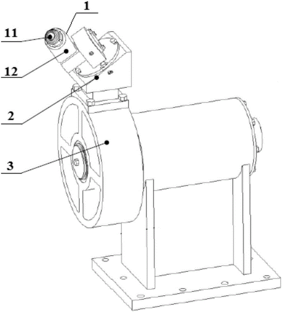
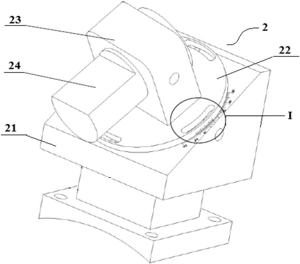
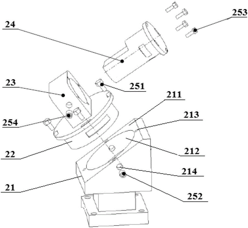
[0068] In order to further simplify the adjustment process of the elevation angle of the pick 11, in the present invention, the elevation angle adjustment mechanism can be arranged on the rotation angle adjustment mechanism. After the rotation angle adjustment mechanism adjusts a certain rotation angle, the elevation angle adjustment mechanism is rotated relative to the rotation angle adjustment mechanism. To realize the adjustment of the elevation angle. Based on this, as an embodiment of the elevation angle adjustment mechanism of the present invention, the elevation angle adjustment mechanism may include a second reference portion 23 and a second adjustment portion 24, wherein: the second reference portion 23 is provided on the first adjustment portion 22, and the The second reference portion 23 has a second axis parallel to the inclined plane 211 and perpendicular to the first axis; the second adjusting portion 24 is used to install the cutting assembly 1, that is, the cutting mounting surface 246 is provided on the second adjusting portion 24, The second adjusting part 24 is rotatably mounted on the second reference part 23 about the second axis, and the cutting mounting surface 246 can rotate with the second adjusting part 24 relative to the second reference part 23 about the second axis , The second adjusting part 24 adjusts the elevation angle of the pick 11 by rotating about the second axis relative to the second reference part 23.
[0069] The elevation angle adjustment mechanism of this embodiment realizes the installation of the elevation angle adjustment mechanism on the rotation angle adjustment mechanism through the second reference portion 23, and the second reference portion 23 can be circulated relative to the first reference portion 21 along with the first adjustment portion 22 The first axis rotates, and the second axis of the second reference portion 23 is always parallel to the inclined plane 211 and always perpendicular to the first axis, forming an adjustment reference for elevation angle adjustment. Since the inclined plane 211 is equivalent to the mounting surface of the tooth seat, the second axis is parallel to the inclined plane 211 and perpendicular to the first axis, and the relative angle between the center line of the pick 12 and the cutting mounting surface 246 remains unchanged. Therefore, the second adjustment The section 24 takes the cutting assembly 1 installed on the cutting mounting surface 246 and rotates around the second axis together to change the angle between the center line of the cutting tooth 11 and the inclined plane 211 (that is, the mounting surface of the tooth seat), so that the elevation angle The adjustment mechanism can adjust the elevation angle of the pick 11. It can be seen that the elevation angle adjustment mechanism of this embodiment can adjust the elevation angle of the pick 11 by rotating the second adjustment portion 24 relative to the second reference portion 23 around the second axis, and has a simple structure and convenient adjustment.
[0070] The rotation of the second adjusting portion 24 relative to the second reference portion 23 can also be achieved by the rotation of the connecting shaft in the mating connecting hole. Based on this, in the present invention, one of the second reference portion 23 and the second adjusting portion 24 includes a second connecting hole 231 and the other includes a second connecting shaft 241 that is fitted with the second connecting hole 231, and the second axis is The central axis of one of the second connecting hole 231 and the second connecting shaft 241 provided on the second reference portion 23, the second connecting shaft 241 and the second connecting hole 231 are sleeved relative to each other about the second axis, so that The second adjusting portion 24 is rotatably mounted on the second reference portion 23 about the second axis, which facilitates the adjustment of the elevation angle of the pick 11.
[0071] Further, in order to solve the problem that the existing cutting test device can only realize the straight cutting mode, the cutting test device of the present invention may also include a mounting base 3 having a direction parallel to the drilling direction of the pick 11 On the third axis, the angle adjusting mechanism 2 is mounted on the mounting base 3, and the mounting base 3 can drive the angle adjusting mechanism 2 to rotate around the third axis. Based on this, the cutting test device of the present invention can not only realize the adjustment of the installation parameters of the pick 11, but also simulate the real rotary cutting method to achieve a cutting test process that is more consistent with the actual cutting process. It is a cutting device The design provides more accurate data support.
[0072] Combine below Figure 1-7 The illustrated embodiments further illustrate the present invention.
[0073] Such as figure 1 As shown, in this embodiment, the cutting test device includes a mounting base 3 and an angle adjustment mechanism 2 mounted on the mounting base 3.
[0074] Among them, the angle adjustment mechanism 2 is used to install the cutting assembly 1 including the pick 11 and the tooth seat 12, and is used to adjust the rotation angle and elevation angle of the pick 1 to adjust the rotation angle parameters and elevation angles required by coal and rock with different characteristics. Parameters are tested and studied. In this embodiment, the angle adjustment mechanism 2 includes a cutting mounting surface 246, a rotation angle adjustment mechanism, and an elevation angle adjustment mechanism. The rotation angle adjustment mechanism is provided on the mounting base 3, and the elevation angle adjustment mechanism is provided on the rotation angle adjustment mechanism. The mounting surface 246 is arranged on the rotation angle adjusting mechanism, and the cutting assembly 1 is mounted on the cutting mounting surface 246, that is, in this embodiment, the cutting assembly 1 is mounted on the elevation angle adjusting mechanism.
[0075] Such as figure 2 As shown, the rotation angle adjustment mechanism of this embodiment includes a first reference portion 21, a first adjustment portion 22, and a rotation angle positioning structure. The first reference portion 21 is provided on the mounting base 3 to realize the rotation angle adjustment mechanism on the mounting base 3. The first adjustment part 22 can adjust the rotation angle of the pick 11 by rotating relative to the first reference part 21; the rotation angle positioning structure is used to rotate the first adjustment part 22 relative to the first reference part 21 as needed The positioning of the first adjusting part 22 on the first reference part 21 is realized when the angle is adjusted, so that the adjusted angle of the pick 11 can remain unchanged until the next angle adjustment, so as to facilitate the adjustment of the cutting assembly 1 under a certain angle parameter. Conduct cutting test research.
[0076] The first reference portion 21 is used to determine the chamfer of the pick 11 and provide an adjustment reference for the first adjustment portion 22 to adjust the angle of rotation. Specifically, such as image 3 As shown, in this embodiment, the first reference portion 21 includes an inclined plane 211 and a first connecting hole 212, wherein: the inclined plane 211 is arranged obliquely with respect to the drilling direction of the pick 11, and the inclined plane 211 and the pick 11 The included angle between the drilling directions is the complementary angle of the chamfer of the pick 11, the inclined plane 211 thus set is parallel to the turning generatrix of the cutting head, and the inclined plane 211 is equivalent to the tooth seat mounting surface; the first connecting hole 212 The central axis is perpendicular to the inclined plane 211, so that the central axis of the first connecting hole 212 becomes the first axis perpendicular to the inclined plane 211 (the tooth seat mounting surface). Therefore, from the definition of the pick chamfer, the first axis and The angle between the drilling direction of the pick 11 (cutting head rotation centerline) is the chamfer of the pick 11, which realizes the determination of the chamfer of the pick 11, so that the first adjustment part 22 can refer to the first connecting hole. 212 rotates to adjust the angle of pick 11. Moreover, by image 3 It can be seen that the first connecting hole 212 of this embodiment penetrates the inclined plane 211, that is, the first connecting hole 212 has an opening located on the inclined plane 211, which facilitates the insertion of the first adjusting portion 22 into the first connecting hole 212. And it is convenient to realize the positioning of the first adjusting portion 22 on the first reference portion 21.
[0077] The first adjusting portion 22 is rotatably disposed about the first axis relative to the first reference portion 21 to realize the adjustment of the rotation angle of the pick 11. Specifically, such as image 3 with Figure 4 As shown, in this embodiment, the first adjusting portion 22 includes a first connecting shaft 221, and the first connecting shaft 221 and the first connecting hole 211 are relatively rotatably sleeved around a first axis, so that the first connecting shaft 221 After being inserted into the first connecting hole 211, it can be rotated in the first connecting hole 211, thereby realizing the rotation of the first adjusting portion 22 relative to the first reference portion 21 about the first axis, and changing the rotation angle of the pick 11.
[0078] Since the inclined plane 211 is equivalent to the mounting surface of the tooth seat, the intersection of the inclined plane 211 and the plane perpendicular to the centerline of rotation of the cutting head is the intersection of the mounting surface of the tooth seat and the plane perpendicular to the center of rotation of the cutting head. Therefore, after the inclined plane 211 is determined, the direction of the line of intersection can be determined; and because the projection line of the center line of the pick 11 on the cutting mounting surface 246 is equivalent to the projection line of the center line of the pick 11 on the bottom surface of the tooth seat , And the first axis is perpendicular to the inclined plane 211. Therefore, the first adjusting portion 22 rotates around the first axis with the cutting assembly 1 installed on the cutting mounting surface 246, which can change the centerline of the pick 11 Cut the angle between the projection line on the installation surface 246 (the bottom surface of the tooth seat) and the intersection line of the plane perpendicular to the rotation center line of the cutting head and the tooth seat installation surface (inclined plane 211) to achieve the 11 corner Adjustment.
[0079] Of course, in other embodiments of the present invention, the first reference portion 21 may include the first connecting shaft 221 and the first adjusting portion 22 may include the first connecting hole 212, as long as the two can cooperate with each other to realize the first adjusting portion 22 is opposite. The rotation of the first reference portion 21 around the first axis is sufficient.
[0080] The corner positioning structure is used to realize the positioning of the first adjusting portion 22 on the first reference portion 21. The corner positioning structure of this embodiment includes a first axial positioning structure and a first circumferential positioning structure, wherein the first axial positioning structure is used for the first adjustment portion 22 relative to the first reference portion 21 around the first axis. When the required angle is rotated, the positioning of the first adjusting portion 22 on the first reference portion 21 along the axial direction of the first connecting hole 212 (that is, the first axis direction) is realized; the first circumferential positioning structure is used for the first adjustment When the portion 22 rotates through the required angle relative to the first reference portion 21 around the first axis, the first adjustment portion 22 is realized on the first reference portion 21 in the circumferential direction of the first connecting hole 212 (that is, the direction of rotation around the first axis). ) On the positioning.
[0081] By providing the first axial positioning structure and the first circumferential positioning structure, when the first adjusting portion 22 is adjusted by rotating a predetermined angle about the first axis relative to the first reference portion 21 to obtain the required turning angle of the pick 11, The first axial positioning structure is used to limit the displacement of the first adjustment part 22 in the first axis direction, and the first circumferential positioning structure is used to limit the displacement of the first adjustment part 22 in the direction of rotation around the first axis to achieve the first The fixation of the adjusting portion 22 on the first reference portion 21 enables the adjusted pick 11 corner to remain unchanged until the next corner adjustment, ensuring the stability of the cutting test process under the corner parameters.
[0082] Such as image 3 with Figure 4 As shown, in this embodiment, the first axial positioning structure includes a first axial positioning hole 213, a first axial waist-shaped hole 223 and a first axial locking member, wherein: the first axial positioning hole 213 is provided On the first reference portion 21, the first axial waist-shaped hole 223 is correspondingly provided on the first adjustment portion 22, and the depth directions of the first axial positioning hole 213 and the first axial waist-shaped hole 223 are along the first The direction of the axis, and in the direction of rotation around the first axis, the first axial waist-shaped hole 223 has a larger size than the first axial positioning hole 213; the first axial locking member is used to insert the first axial positioning hole 213 And the first axial waist hole 223.
[0083] Since the depth directions of the first axial positioning hole 213 and the first axial waist-shaped hole 223 are both along the direction of the first axis, the first axial locking member is inserted into the first axial positioning hole 213 and the first axial direction. After the waist-shaped hole 223 is inserted, the first adjustment portion 22 can no longer move along the first axis, and the positioning of the first adjustment portion 22 on the first reference portion 21 along the first axis direction can be realized. Moreover, since the first axial waist-shaped hole 223 has a larger size than the first axial positioning hole 213 in the direction of rotation around the first axis, the first adjustment portion 22 is relative to the first reference around the first axis. During the rotation of the portion 21, that is, when the first adjusting portion 22 adjusts the angle of the pick 11, the first axial waist-shaped hole 223 can always be well aligned with the first axial positioning hole 213, so that the After the rotation angle is adjusted, the positioning of the first adjusting portion 22 along the first axis direction can be conveniently realized.
[0084] Moreover, in order to achieve more accurate positioning of the first adjustment portion 22 along the first axis direction, such as Figure 2-4 As shown, in this embodiment, the first adjusting portion 22 further includes a first flange portion 222, which is provided at the end of the first connecting shaft 221, and when the first connecting shaft 221 is inserted into the When in a connecting hole 212, the first flange portion 222 is attached to the inclined plane 211. By the attachment of the first flange portion 222 to the inclined plane 221, the displacement of the first adjustment portion 22 along the first axis can be further restricted, and the positioning accuracy of the first adjustment portion 22 along the first axis direction can be improved.
[0085] Specifically, by image 3 with Figure 4 It can be seen that the first axial positioning hole 213 is provided on the inclined plane 211 and the first axial waist-shaped hole 223 is correspondingly provided on the first flange portion 222. Since the inclined plane 211 is attached to the first flange portion 222, the first axial positioning hole 213 is arranged on the inclined plane 211, and the first axial waist hole 223 is arranged on the first flange portion 222 Therefore, the alignment of the first axial positioning hole 213 and the first axial waist-shaped hole 223 can be realized more conveniently, and the first axial locking member can be inserted into it to realize the positioning of the first adjusting portion 22 along the first axis direction.
[0086] More specifically, the first axial positioning hole 213 is a circular threaded hole; the first axial waist hole 223 is an oblong arc hole arranged concentrically with the cross section of the first connecting shaft 221; and the first axial locking member is The first bolt 251 fits with the first axial positioning hole 213 and the first axial waist hole 223. Based on this, when the first connecting shaft 221 adjusts the angle of the pick 11 by rotating the first connecting hole 212 by the required angle around the first axis, the first bolts 251 are sequentially inserted into the first axial waist shape aligned with each other. In the hole 223 and the first axial positioning hole 213, the positioning of the first adjusting portion 22 on the first reference portion 21 along the first axis direction can be realized, with a simple structure and convenient positioning. In addition, the first axial waist-shaped hole 223 adopts an oblong arc-shaped hole, which can better adapt to the rotation of the first connecting shaft 221 about the first axis compared with other structural forms such as oblong holes, so that it can be more Accurately maintain the set angle of pick 11 until the next adjustment.
[0087] Such as image 3 with Figure 4 As shown, in this embodiment, the first axial positioning structure includes a plurality of first axial positioning holes 213, a plurality of first axial waist-shaped holes 223, and a plurality of first bolts 251. The holes 223 and the first bolts 251 are the same in number as the first axial positioning holes 213 and are arranged in one-to-one correspondence with the first axial positioning holes 213. Each of the first axial positioning holes 213 is along the first connecting hole 213. The circumferential interval of each first axial waist-shaped hole 223 is evenly distributed on the first flange portion 222 along the circumferential interval of the first connecting shaft 221, so that the alignment can be achieved. An adjustment portion 22 is positioned more firmly and accurately along the first axis direction.
[0088] Such as image 3 with Figure 4 As shown, in this embodiment, the first circumferential positioning structure includes a first circumferential positioning hole 214, a first circumferential waist-shaped hole 224 and a first circumferential locking member, wherein: the first circumferential positioning hole 214 is provided On the first reference portion 21, a first circumferential waist-shaped hole 224 is correspondingly provided on the first adjustment portion 22, and the depth direction of the first circumferential positioning hole 214 and the first circumferential waist-shaped hole 224 are both along the first The radial direction of the connecting hole 212 (that is, both perpendicular to the first axis and perpendicular to the direction of rotation about the first axis), and on the first circumference of the first connecting hole 212 (the direction of rotation about the first axis) The waist-shaped hole 224 has a size larger than that of the first circumferential positioning hole 214; the first circumferential locking member is used for inserting into the first circumferential positioning hole 214 and the first circumferential waist-shaped hole 224.
[0089] Since the depth directions of the first circumferential positioning hole 214 and the first circumferential waist hole 224 are along the radial direction of the first connecting hole 212, the first circumferential locking member is inserted into the first circumferential positioning hole 214 and the After being in the circumferential waist-shaped hole 224, the first adjusting portion 22 can no longer move along the circumferential direction of the first connecting hole 212, so that the first adjusting portion 22 is along the first connecting hole on the first reference portion 21 212 circumferential positioning. Moreover, since the first circumferential waist-shaped hole 224 has a larger size than the first circumferential positioning hole 214 in the circumferential direction of the first connecting hole 212, the first adjusting portion 22 is relative to the first axis around the first axis. During the rotation of a reference part 21, that is, when the first adjusting part 22 adjusts the angle of the pick 11, the first circumferential waist hole 224 can always be well aligned with the first circumferential positioning hole 214, so that The positioning of the first adjusting portion 22 along the circumferential direction of the first connecting hole 212 can be conveniently realized after the rotation angle is adjusted.
[0090] Specifically, by image 3 with Figure 4 It can be seen that the first circumferential positioning hole 214 is disposed on the side wall of the first connecting hole 212, and the first circumferential waist-shaped hole 224 is correspondingly disposed on the side wall of the first connecting shaft 221. This facilitates the alignment of the first circumferential positioning hole 214 with the first circumferential waist hole 224 and the insertion and positioning of the first circumferential locking member.
[0091] More specifically, the first circumferential positioning hole 214 is a circular threaded hole; the first circumferential waist-shaped hole 224 is an oblong arc hole concentric with the cross section of the first connecting shaft 221; the first circumferential locking member is a Two bolts 252 are matched with the first circumferential positioning hole 214 and the first circumferential waist hole 224. Based on this, when the first connecting shaft 221 adjusts the angle of the pick 11 by rotating the first connecting hole 212 by the required angle around the first axis, the second bolts 252 are sequentially inserted into the first circumferential positioning holes aligned with each other. 214 and the first circumferential waist hole 224, the positioning of the first adjusting portion 22 on the first reference portion 21 along the circumferential direction of the first connecting hole 212 can be conveniently realized. And, similar to the first axial waist-shaped hole 223, the first circumferential waist-shaped hole 224 adopts an oblong arc hole, which can better adapt to the rotation of the first connecting shaft 221 around the first axis, so that it can be more accurate Keep the set angle of pick 11 until the next adjustment.
[0092] In addition, in order to reduce the risk of failure of the first circumferential positioning structure when the pick 11 is impacted, in this embodiment, the first circumferential waist-shaped hole 224 is set as a blind hole, and the first circumferential waist-shaped hole The depth of 224 is set to gradually decrease along the direction opposite to the rotation direction of the first axis under the action of the tangential force of the first connecting shaft 221 (ie, the first adjusting portion 22) when the pick 11 cuts. During the cutting process, especially when impacted, the pick 11 will be subjected to lateral force, radial force and tangential force. The tangential force will cause the cutting assembly 1 to drive the first connecting shaft 221 (first adjustment Part 22) together produce a rotation trend in a certain direction around the first axis (the direction of the rotation trend is consistent with the direction of the tangential force, in Figure 1-4 The middle is the clockwise direction when viewed from above), so that the first circumferential locking member in the first circumferential waist-shaped hole 224 has a movement trend opposite to the direction of the first connecting shaft 221 (the first adjusting portion 22) (in Figure 1-4 The middle is the counterclockwise direction when viewed from above). Therefore, in this embodiment, the first circumferential waist-shaped hole 224 is set to a depth along the first connecting shaft 221 (the first adjusting portion 21) and it goes around the second under the action of a tangential force. The opposite direction of the one-axis rotation direction is gradually reduced, and the structural feature of the gradually shallower depth of the first waist-shaped hole 224 can be used to limit the movement tendency of the first circumferential locking member in the first circumferential waist-shaped hole 224 when impacted. , So that the first circumferential positioning structure can still play a better role in the circumferential positioning, to prevent the first circumferential positioning structure positioning failure when the pick 11 is impacted, the first adjustment portion 22 and the cutting assembly 1 due to Rotation occurs due to tangential force.
[0093] Based on the rotation angle adjustment structure of this embodiment, the rotation angle of the pick 11 can be adjusted according to the following steps:
[0094] (1) Insert the first connecting shaft 221 into the first connecting hole 212, and rotate the first connecting shaft 221 to the required position according to the required angle, so that the turning angle of the pick 11 is adjusted to the turning angle to be tested;
[0095] (2) Then, pass the first bolt 251 through the first axial waist-shaped hole 223 and screw into the first axial positioning hole 213 to lock it, restricting the movement of the first adjusting portion 22 along the first axis direction, and The second bolt 252 is screwed into the first circumferential positioning hole 224 and inserted into the first circumferential waist hole 224 to be locked, restricting the rotation of the first adjusting portion 22 in the circumferential direction of the first connecting hole 212, so that the first adjusting portion 22 It is fixed on the first reference part 21 and keeps the set rotation angle of the pick 11 unchanged, and performs a cutting test until the next rotation angle adjustment.
[0096] In order to facilitate the identification of the adjusted turning angle during the above-mentioned turning angle adjustment process, in this embodiment, the turning angle adjusting mechanism further includes a turning angle marking structure for marking the turning angle adjusted by the turning angle adjusting mechanism. By setting the corner indicator structure, not only can the size of the adjusted corner be clearly shown for easy adjustment, but also the corner adjustment range can be limited, so that the corner adjustment mechanism can perform more accurate corner adjustment within the required angle range, for example, the corner can be adjusted The adjustment range of the rotation angle of the adjustment mechanism is ±15°. The angle adjustment mechanism adjusts the angle of the pick 11 to change within the range of ±15°, which is more in line with the actual cutting test requirements.
[0097] Specifically, combine figure 2 , Figure 4 with Image 6 It can be seen that the corner marking structure of this embodiment includes a first corner scale portion 215 provided on the first reference portion 21 (specifically, the inclined plane 211) and a first adjustment portion 22 (specifically, the first flange portion 222). The second corner scale part 225, the first corner scale part 215 and the second corner scale part 225 on the side wall are all arranged along the rotation direction around the first axis. The second corner scale portion 225 of this embodiment can rotate relative to the first corner scale portion 215 as the first adjustment portion 22 rotates relative to the first reference portion 21, the first corner scale portion 215 and the second corner scale portion 225 is equivalent to the main ruler and the vernier of the vernier caliper, and the two cooperate with each other to achieve a higher-precision angle adjustment process, for example, the angle adjustment accuracy can reach 0.1°. The adjusting accuracy of the turning angle adjustment mechanism for the turning angle of the pick 11 is set to 0.1°, which is more helpful for the cutting test device to more accurately match the turning angle parameters with the actual cutting requirements.
[0098] Such as Figure 2-5 As shown, the elevation angle adjustment mechanism of this embodiment includes a second reference portion 23, a second adjustment portion 24, and an elevation angle positioning structure, wherein: the second reference portion 23 is provided on the first adjustment portion 22, so that the elevation angle adjustment mechanism can adjust the rotation angle The installation on the mechanism; the cutting mounting surface 246 is provided on the second adjusting portion 24, so that the second adjusting portion 24 is used to install the cutting assembly 1, and the second adjusting portion 24 can be rotated relative to the second reference portion 23 The elevation angle of the pick 11 is adjusted; the elevation angle positioning structure is used to realize the positioning of the second adjustment portion 24 on the second reference portion 23 when the second adjustment portion 24 is rotated by a required angle relative to the second reference portion 23, Therefore, the adjusted elevation angle of the pick 11 can remain unchanged until the next elevation angle adjustment, so as to facilitate the cutting test study on the cutting assembly 1 under a certain elevation angle parameter.
[0099] The second reference portion 23 is used to provide an adjustment reference for the second adjustment portion 24 to adjust the elevation angle. Specifically, such as image 3 with Figure 4 As shown, in this embodiment, the second reference portion 23 is fixed on the first flange portion 222 of the first adjustment portion 22, and includes a first plane, a second plane and a second connecting hole 231, wherein: the first The plane and the second plane are opposed to each other along the direction parallel to the inclined plane 211 and perpendicular to the first axis, and the first plane is located upstream of the second plane along the drilling direction of the pick 11 image 3 The first plane is the right plane of the second reference portion 23, and the second plane is the left plane of the second reference portion 23; the central axis of the second connecting hole 231 is perpendicular to the first and second planes, so that the The central axis of the second connecting hole 231 becomes a second axis that is parallel to the inclined plane 211 and perpendicular to the first axis, so that the second adjusting portion 24 can rotate with reference to the second connecting hole 231 to adjust the elevation angle of the pick 11. Moreover, by image 3 It can be seen that the second connecting hole 231 of this embodiment penetrates the first plane and the second plane, which facilitates the insertion of the second adjusting portion 24 into the second connecting hole 231, and facilitates the realization of the second adjusting portion 24 at the second reference Positioning on section 23.
[0100] The second adjusting portion 24 is rotatably disposed about the second axis relative to the second reference portion 23 to adjust the elevation angle of the pick 11 of the cutting assembly 1 mounted thereon. Specifically, such as image 3 with Figure 5 As shown, in this embodiment, the second adjusting portion 24 includes a second connecting shaft 241, and the second connecting shaft 241 and the second connecting hole 231 are relatively rotatably sleeved around a second axis, so that the second connecting shaft 241 After being inserted into the second connecting hole 231, it can be rotated in the second connecting hole 231, thereby realizing the rotation of the second adjusting portion 24 relative to the second reference portion 23 about the second axis, and changing the elevation angle of the pick 11.
[0101] Since the inclined plane 211 is equivalent to the mounting surface of the tooth seat, and the relative angle between the center line of the pick 12 and the cutting mounting surface 246 remains unchanged, the second adjusting portion 24 carries the cutting mounted on the cutting mounting surface 246. The assembly 1 rotates together around a second axis parallel to the inclined plane 211 and perpendicular to the first axis to change the angle between the center line of the pick 11 and the inclined plane 211 (that is, the mounting surface of the tooth holder), so that the elevation angle can be adjusted The mechanism can realize the adjustment of the elevation angle of the pick 11.
[0102] by Figure 1-3 It can be seen that, in this embodiment, the cutting mounting surface 246 is provided on the side wall of the second connecting shaft 241, and the cutting mounting surface 246 is parallel to the second axis. In this way, it is convenient to cut the mounting surface 246 and the cutting assembly 1 installed on the cutting mounting surface 246 to rotate around the first axis along with the first adjusting part 22 to adjust the angle of the pick 11, and it is also convenient to cut the mounting surface 246 and the cutting assembly 1 installed on the cutting mounting surface 246 rotate with the second adjusting part 24 around the second axis to adjust the elevation angle of the pick 11.
[0103] Of course, the cutting mounting surface 246 is not limited to being provided on the second connecting shaft 241. For example, when the angle adjusting mechanism 2 only realizes the adjustment of the turning angle of the pick 11, the cutting mounting surface 246 can also be directly provided on the second connecting shaft 241. On one adjustment portion 22, it is sufficient that the cutting mounting surface 246 is parallel to an axis parallel to the inclined plane 211 and perpendicular to the first axis. Moreover, in other embodiments of the present invention, the second reference portion 23 may also include the second connecting shaft 241 and the second adjusting portion 24 may include the second connecting hole 231, as long as the two can cooperate with each other to realize the second adjusting portion 24 facing each other. The rotation of the second reference portion 23 around the second axis is sufficient.
[0104] The elevation angle positioning structure is used to realize the positioning of the second adjusting portion 24 on the second reference portion 23. The elevation angle positioning structure of this embodiment includes a second axial positioning structure and a second circumferential positioning structure, wherein the second axial positioning structure is used for the second adjustment portion 24 relative to the second reference portion 23 around the second axis. The positioning of the second adjusting portion 24 along the axial direction of the second connecting hole 231 (that is, the second axis direction) on the second reference portion 23 is realized when the required angle is rotated; the second circumferential positioning structure is used for the second adjustment When the part 24 is rotated around the second axis relative to the second reference part 23 through the required angle, the second adjustment part 24 is realized on the second reference part 23 in the circumferential direction of the second connecting hole 231 (that is, the direction of rotation around the second axis). ) On the positioning.
[0105] By providing the second axial positioning structure and the second circumferential positioning structure, when the second adjusting portion 24 is adjusted to obtain the required elevation angle of the pick 11 by rotating a predetermined angle relative to the second reference portion 23 around the second axis, The second axial positioning structure is used to restrict the displacement of the second adjustment portion 24 in the second axis direction, and the second circumferential positioning structure is used to restrict the displacement of the second adjustment portion 24 in the rotation direction about the second axis, so as to realize the first The fixation of the second adjusting part 24 on the second reference part 23 enables the adjusted elevation angle of the pick 11 to remain unchanged until the next elevation angle adjustment, ensuring the stability of the cutting test process under a certain elevation angle parameter condition.
[0106] Such as Figure 3-5 As shown, in this embodiment, the second axial positioning structure includes a second axial positioning hole 232, a second axial waist-shaped hole 243 and a second axial locking member, wherein: the second axial positioning hole 232 is provided On the second reference portion 23, the second axial waist-shaped hole 243 is correspondingly provided on the second adjusting portion 24, and the depth direction of the second axial positioning hole 232 and the second axial waist-shaped hole 243 are both along the second The direction of the axis, and in the direction of rotation about the second axis, the second axial waist-shaped hole 243 has a size larger than the second axial positioning hole 232; the second axial locking member is used to insert the second axial positioning hole 232 And the second axial waist-shaped hole 243.
[0107] Since the depth directions of the second axial positioning hole 232 and the second axial waist-shaped hole 243 are along the direction of the second axis, the second axial locking member is inserted into the second axial positioning hole 232 and the second axial direction. After the waist-shaped hole 243 is inserted, the second adjustment portion 24 can no longer move along the second axis, and the positioning of the second adjustment portion 24 on the second reference portion 23 along the second axis direction can be realized. Moreover, since the second axial waist-shaped hole 243 has a larger size than the second axial positioning hole 232 in the direction of rotation about the second axis, the second adjustment portion 24 is relative to the second reference around the second axis. During the rotation of the portion 23, that is, when the second adjusting portion 24 adjusts the elevation angle of the pick 11, the second axial waist hole 243 can always be well aligned with the second axial positioning hole 232, so that the After the elevation angle is adjusted, the positioning of the second adjusting portion 24 along the second axis direction can be conveniently realized.
[0108] Moreover, in order to achieve a more accurate positioning of the second adjustment portion 24 along the second axis direction, such as Figure 2-5 As shown, in this embodiment, the second adjusting portion 24 further includes a second flange portion 242, which is provided at the end of the second connecting shaft 241, and when the second connecting shaft 241 is inserted into the When in the two connecting holes 231, the second flange portion 242 is attached to the first plane. Through the attachment of the second flange portion 242 to the first plane, the displacement of the second adjustment portion 24 along the second axis can be further restricted, and the positioning accuracy of the second adjustment portion 24 along the second axis direction can be improved.
[0109] Specifically, by Figure 2-5 It can be seen that the second axial positioning hole 232 is provided on the first plane, and the second axial waist-shaped hole 243 is correspondingly provided on the second flange portion 242. Since the first plane is attached to the second flange portion 242, the second axial positioning hole 232 is arranged on the first plane 211, and the second axial waist hole 243 is arranged on the second flange portion 242 Above, the alignment of the second axial positioning hole 232 and the second axial waist-shaped hole 243 can be achieved more conveniently, and the second axial locking member can be inserted into it to realize the positioning of the second adjusting portion 24 along the second axis direction.
[0110] More specifically, the second axial positioning hole 232 is a circular threaded hole; the second axial waist-shaped hole 243 is an oblong arc-shaped hole arranged concentrically with the cross section of the second connecting shaft 241; the second axial locking member is The third bolt 253 fits with the second axial positioning hole 232 and the second axial waist hole 243. Based on this, when the second connecting shaft 241 rotates the required angle of the pick 11 relative to the second connecting hole 231 around the second axis to adjust the elevation angle of the pick 11, the third bolts 253 are sequentially inserted into the second axial waist shape aligned with each other. In the hole 243 and the second axial positioning hole 232, the positioning of the second adjusting portion 24 on the second reference portion 23 along the second axis direction can be realized, with a simple structure and convenient positioning. In addition, the second axial waist-shaped hole 243 adopts an oblong arc-shaped hole, which can better adapt to the rotation of the second connecting shaft 241 around the second axis compared with other structural forms such as oblong holes. Accurately maintain the adjusted elevation angle of the pick 11 until the next adjustment.
[0111] Such as Figure 4 with Figure 5 As shown, in this embodiment, the second axial positioning structure includes a plurality of second axial positioning holes 232, a plurality of second axial waist-shaped holes 243 and a plurality of third bolts 253, the second axial waist-shaped The holes 243 and the third bolts 253 are the same in number as the second axial positioning holes 232 and are arranged in one-to-one correspondence with the second axial positioning holes 232. Each of the second axial positioning holes 232 is along the first connecting hole 213. The circumferential interval of each second axial waist-shaped hole 243 is evenly distributed on the second flange portion 242 along the circumferential interval of the second connecting shaft 241, so that the second flange portion 242 can be evenly distributed on the first plane. The second adjusting portion 24 is positioned more firmly and accurately along the second axis direction.
[0112] Such as figure 2 , image 3 with Figure 5 As shown, in this embodiment, the second circumferential positioning structure includes a second circumferential positioning hole 233, a second circumferential waist hole 244 and a second circumferential locking member, wherein: the second circumferential positioning hole 233 is provided On the second reference portion 23, the second circumferential waist hole 244 is correspondingly provided on the second adjustment portion 24, and the depth direction of the second circumferential positioning hole 233 and the second circumferential waist hole 244 are both along the second The radial direction of the connecting hole 231 (that is, both perpendicular to the second axis and perpendicular to the direction of rotation about the second axis), and on the second circumference of the second connecting hole 231 (the direction of rotation about the second axis) The waist-shaped hole 244 has a larger size than the second circumferential positioning hole 233; the second circumferential locking member is used to be inserted into the second circumferential positioning hole 233 and the second circumferential waist-shaped hole 244.
[0113] Since the depth directions of the second circumferential positioning hole 233 and the second circumferential waist hole 244 are along the radial direction of the second connecting hole 231, the second circumferential locking member is inserted into the second circumferential positioning hole 233 and the second circumferential positioning hole 233 After the two circumferential waist-shaped holes 244 are inserted, the second adjusting portion 24 can no longer move along the circumferential direction of the second connecting hole 231, so that the second adjusting portion 24 is along the second connecting hole on the second reference portion 23 231 circumferential positioning. Moreover, since the second circumferential waist-shaped hole 244 has a larger size than the second circumferential positioning hole 233 in the circumferential direction of the second connecting hole 231, the second adjusting portion 24 is relative to the second axis around the second axis. During the rotation of the second reference portion 23, that is, when the second adjusting portion 24 adjusts the elevation angle of the pick 11, the second circumferential waist hole 244 can always be well aligned with the second circumferential positioning hole 233, thereby The positioning of the second adjusting portion 24 along the circumferential direction of the second connecting hole 231 can be conveniently realized after the elevation angle is adjusted.
[0114] Specifically, by Figure 4 with Figure 5 It can be seen that the second circumferential positioning hole 233 is provided on the side wall of the second connecting hole 231, and the second circumferential waist hole 244 is correspondingly provided on the side wall of the second connecting shaft 241. This is more convenient for the alignment of the second circumferential positioning hole 233 with the second circumferential waist-shaped hole 244 and the insertion and positioning of the second circumferential locking member.
[0115] More specifically, the second circumferential positioning hole 233 is a circular threaded hole; the second circumferential waist-shaped hole 244 is an oblong arc-shaped hole concentric with the cross section of the second connecting shaft 241; the second circumferential locking member is a first Four bolts 254, which are matched with the second circumferential positioning hole 233 and the second circumferential waist hole 244. Based on this, when the second connecting shaft 241 adjusts the elevation angle of the pick 11 by rotating the second connecting hole 231 by the required angle around the second axis, the fourth bolt 254 is sequentially inserted into the second circumferential positioning holes aligned with each other. 233 and the second circumferential waist-shaped hole 244 can conveniently realize the positioning of the second adjusting portion 24 on the second reference portion 23 along the circumferential direction of the second connecting hole 231. And, similar to the second axial waist-shaped hole 243, the second circumferential waist-shaped hole 244 adopts an oblong arc-shaped hole, which can better adapt to the rotation of the second connecting shaft 241 around the second axis, so that it can be more accurate Keep the set elevation angle of the pick 11 until the next adjustment.
[0116] In addition, in order to reduce the risk of failure of the second circumferential positioning structure when the pick 11 is impacted, in this embodiment, the second circumferential waist-shaped hole 244 is set as a blind hole, and the second circumferential waist-shaped hole 244 is arranged such that its depth gradually decreases along the direction opposite to the direction of rotation of the second connecting shaft 241 (ie, the second adjusting portion 24) that is subjected to the tangential force when the pick 11 cuts. As mentioned above, when subjected to an impact, the tangential force received by the pick 11 will cause the cutting assembly 1 to drive the second connecting shaft 241 (second adjustment portion 24) to rotate in a certain direction around the second axis. Trend (the direction of the rotation trend is consistent with the direction of the tangential force, in Figure 5 The middle is the clockwise direction when viewed from above), so that the second circumferential locking member in the second circumferential waist-shaped hole 244 has a movement trend that is opposite to the direction of the second connecting shaft 241 (the second adjusting portion 24) (in Figure 5 The middle is the counterclockwise direction when viewed from above). Therefore, in this embodiment, the second circumferential waist-shaped hole 244 is set to a depth along the second connecting shaft 241 (the second adjusting portion 24) around the first under tangential force. The opposite direction of the two-axis rotation direction is gradually reduced, and the structural feature of the gradually shallower depth of the first waist-shaped hole 224 can be used to limit the movement tendency of the second circumferential locking member in the second circumferential waist-shaped hole 244 under impact , So that the second circumferential positioning structure can still play a better role in the circumferential positioning, to prevent the second circumferential positioning structure positioning failure when the pick 11 is impacted, the second adjustment portion 24 and the cutting assembly 1 due to Rotation occurs due to tangential force.
[0117] Based on the elevation angle adjustment structure of this embodiment, the elevation angle of the pick 11 can be adjusted according to the following steps:
[0118] (1) Insert the second connecting shaft 241 into the second connecting hole 231, and rotate the second connecting shaft 241 to the required position according to the required angle, so that the elevation angle of the pick 11 is adjusted to the elevation angle to be tested;
[0119] (2) Then, the third bolt 253 is passed through the second axial waist hole 243 and screwed into the second axial positioning hole 232 to lock it, restricting the movement of the second adjusting portion 24 in the second axis direction, and The fourth bolt 254 is screwed into the first circumferential positioning hole 224 and inserted into the second circumferential waist-shaped hole 244 to be locked, restricting the rotation of the second adjusting portion 24 in the circumferential direction of the second connecting hole 231, so that the second adjusting portion 24 It is fixed on the second reference part 23, keeps the set elevation angle of the pick 11 unchanged, and performs a cutting test until the next elevation angle adjustment.
[0120] In order to facilitate the identification of the adjusted elevation angle during the above-mentioned elevation angle adjustment process, in this embodiment, the elevation angle adjustment mechanism further includes an elevation angle marking structure for indicating the elevation angle adjusted by the elevation angle adjustment mechanism. By setting the elevation angle indicator structure, not only can the size of the adjusted elevation angle be clearly shown for easy adjustment, but also the elevation angle adjustment range can be limited, so that the elevation angle adjustment mechanism can perform more accurate elevation angle adjustment within the required angle range, for example, the elevation angle can be adjusted The elevation angle adjustment range of the adjustment mechanism is 40-65°. The elevation angle adjustment mechanism adjusts the elevation angle of the pick 11 to change within the range of 40-65°, which is more in line with the actual cutting test requirements.
[0121] Specifically, combine figure 2 , Figure 4 with Figure 5 It can be seen that the elevation angle marking structure of this embodiment includes a first elevation angle scale portion 234 provided on the second reference portion 23 (specifically the first plane) and a second adjustment portion 24 (specifically the second flange portion 242). The second elevation angle scale part 245, the first elevation angle scale part 234 and the second elevation angle scale part 245 on the side wall are all arranged along the rotation direction around the second axis. The second elevation angle scale part 245 of this embodiment can rotate relative to the first elevation angle scale part 234 as the second adjustment part 24 rotates relative to the second reference part 23, the first elevation angle scale part 234 and the second elevation angle scale part 245 is respectively equivalent to the main ruler and vernier of the vernier caliper. The two cooperate with each other to realize a higher-precision elevation angle adjustment process, for example, the elevation angle adjustment accuracy can reach 0.1°. The adjustment accuracy of the elevation angle adjustment mechanism for the elevation angle of the pick 11 is set to 0.1°, which is more helpful for the cutting test device to more accurately match the elevation angle parameters with the actual cutting requirements.
[0122] The mounting base 3 is used to carry the angle adjustment mechanism 2 and is used to drive the angle adjustment mechanism 2 to rotate. Since the cutting assembly 1 is installed on the angle adjusting mechanism 2, the mounting base 3 can drive the cutting assembly 1 to rotate by driving the angle adjusting mechanism 2 to rotate, so as to realize the rotary cutting test method and simulate the actual cutting process more accurately. Obtain more accurate test data.
[0123] Combine figure 1 with Figure 7 It can be seen that the mounting base 3 of this embodiment includes a frame 31 and a rotating mechanism. The frame 31 is supported below the rotating mechanism to provide support for the rotating mechanism; the rotating mechanism is installed on the frame 31 and has a drill parallel to the pick 11 The rotation mechanism can rotate relative to the frame 31 around the third axis, and the angle adjustment mechanism 2 is installed on the rotation mechanism, so that when the rotation mechanism rotates around the third axis, the angle adjustment mechanism 2 and installation can be driven The cutting assembly 1 on the angle adjusting mechanism 2 rotates together around the third axis. Since the third axis is parallel to the drilling direction of the pick 11, the third axis is equivalent to the centerline of rotation of the cutting head body. Therefore, the rotation mechanism drives the angle adjustment mechanism 2 and the cutting mounted on the angle adjustment mechanism 2 The assembly 1 rotates around the third axis together, and the actual rotary cutting mode can be modeled.
[0124] Specifically, the rotating mechanism includes a transmission shaft 32 and a rotating head body 36, wherein the central axis of the transmission shaft 32 is parallel to the drilling direction of the pick 11, and it is rotatably supported on the bracket 31 around its own central axis, and the rotating head The body 36 is arranged at the end of the drive shaft 32 along the drilling direction of the pick 11, and its central axis is collinear with the central axis of the drive shaft 32, that is, the central axis of the rotating head body 36 is also parallel to the drilling direction of the pick 11 , So that the central axis of the transmission shaft 32 and the rotating head body 36 is the aforementioned third axis; and the angle adjusting mechanism 2 is installed on the rotating head body 36. Based on this, when the drive shaft 32 is driven by a power mechanism (such as a motor) to rotate around the third axis, it can drive the rotating head 36 and the cutting assembly 1 mounted on it to rotate around the third axis to realize the rotary cutting Cut test method.
[0125] In this embodiment, the rotating head body 36 is arranged at the end of the transmission shaft 32 along the drilling direction of the pick 11. The advantage is that it can reduce the interference of the cutting test device on the cutting assembly 1 during the cutting test. It is beneficial to make the pick 11 first enter the rock in both the axial and circumferential directions relative to the cutting test device, and then cooperate with the different drilling directions of the test rig to easily realize the simulation of the two operating states of drilling and yaw. The installation parameters of the pick 11 matched with the drilling and yaw operating states were tested and studied.
[0126] More specifically, this embodiment realizes the rotatable connection between the transmission shaft 32 and the support 31 by providing a support bearing between the transmission shaft 32 and the support 31. Among them, the support bearing can adopt tapered roller bearings 34, which can not only realize the rotatable connection between the transmission shaft 32 and the bracket 31, but also use tapered roller bearings 34 to offset the lateral direction of the pick 11 during the test. It can realize more stable and reliable operation of the cutting test device.
[0127] In addition, the power connection between the rotating head body 36 and the transmission shaft 32 of this embodiment is realized by providing a flat key 33. The flat key 33 can transmit the rotation of the transmission shaft 32 to the rotating head body 36 so that the rotating head body 36 can rotate together with the transmission shaft 32 about the third axis.
[0128] Moreover, in order to better limit the displacement of the transmission shaft 32 and the rotating head body 36 along the third axis, Figure 7 It can be seen that, in this embodiment, the mounting base 3 further includes a first baffle 351, a second baffle 352, a third baffle 353, and a fifth bolt 37, wherein: the first baffle 351 and the second baffle 352 are respectively Is provided at both ends of the transmission shaft 32 along the third axis to limit the displacement of the transmission shaft 32 along the third axis; the third baffle 353 is provided at the end of the rotating shaft 36 away from the transmission shaft 32, and The fifth bolt 37 and the second baffle 352 jointly limit the displacement of the rotating head body 36 along the third axis.
[0129] It can be seen that the cutting test device of this embodiment can not only adjust the rotation angle and elevation angle of the pick 1, but also realize the rotary cutting test method, which has higher test accuracy and is more conducive to improving the cutting performance of the cutting device. Therefore, the cutting efficiency of the cutting device can be improved, and the risk of pick failure can be reduced.
[0130] It should be noted that in other embodiments of the present invention, the positions of the first axial positioning hole 213 and the first axial waist-shaped hole 223 can be interchanged, that is, the first axial positioning hole 213 may be arranged in the first axial positioning hole 213. The first axial waist-shaped hole 223 is provided on the first reference portion 21 on the adjusting portion 22; similarly, the first circumferential positioning hole 214 and the first circumferential waist-shaped hole 224 are arranged at positions and the second axial positioning The positions of the hole 232 and the second axial waist-shaped hole 243, and the second circumferential positioning hole 233 and the second circumferential positioning hole 244 are interchangeable, and these modifications are also within the protection scope of the present invention. .

PUM

no PUM

Description & Claims & Application Information

We can also present the details of the Description, Claims and Application information to help users get a comprehensive understanding of the technical details of the patent, such as background art, summary of invention, brief description of drawings, description of embodiments, and other original content. On the other hand, users can also determine the specific scope of protection of the technology through the list of claims; as well as understand the changes in the life cycle of the technology with the presentation of the patent timeline. Login to view more.

Similar technology patents

Hob driving adjustment and overload protection system for excavation

PendingCN112095704AImprove job performancePrevent drive overload
Owner:施红

Cable tie with foldable head with 2-pass holes

ActiveCN110053874AImprove job performance
Owner:DONG A BESTECH

Four-arm telescopic mechanism of aerial work vehicle

InactiveCN112607678AImprove scaling efficiencyImprove job performance
Owner:XCMG XUZHOU TRUCK MOUNTED CRANE

Catchable packer blocker

ActiveCN106437607AImprove job performanceSimplify the operation process
Owner:牡丹江金恒石油机械科技有限公司

An agricultural pest monitoring method and equipment based on hyperspectrum

ActiveCN113468964AReduce crop disease causes and medication mismatchesImprove job performance
Owner:山东省邮电工程有限公司 +2

Classification and recommendation of technical efficacy words

  • Improve job performance

Manual cutter grinder of silage machine

PendingCN107932206Areduce labor costsImprove job performance
Owner:SHANDONG AGRICULTURAL UNIVERSITY

A method for optimize that performance and evaluating the effect of lubricate drag reduction components

PendingCN109299566AImprove job performanceReduce target level stress
Owner:SHANDONG AGRICULTURAL UNIVERSITY

An agricultural pest monitoring method and equipment based on hyperspectrum

ActiveCN113468964AReduce crop disease causes and medication mismatchesImprove job performance
Owner:山东省邮电工程有限公司 +2

Four-arm telescopic mechanism of aerial work vehicle

InactiveCN112607678AImprove scaling efficiencyImprove job performance
Owner:XCMG XUZHOU TRUCK MOUNTED CRANE
Why Eureka
Try Eureka