
Monitoring device and monitoring method for corrosion of inner wall of pipeline

A monitoring device, a technology for inner wall corrosion, applied in measurement devices, weather resistance/light resistance/corrosion resistance, instruments, etc., can solve the problems of inability to monitor local corrosion, inability to monitor coupling effects, and inability to obtain corrosion information.

Active Publication Date: 2017-05-24
DALIAN UNIV OF TECH
View PDF4 Cites 16 Cited by
  • Summary
  • Abstract
  • Description
  • Claims
  • Application Information

AI Technical Summary

Problems solved by technology

However, in the actual pipeline, there is no independent corrosion area, any occurrence of corrosion has a coupling effect with the surrounding pipeline area, and the monitoring method using circular slice technology only provides the corrosion situation in a certain position of the pipeline. Corrosion information along the direction of the pipeline cannot be obtained, that is, local corrosion problems along the direction of the pipeline cannot be monitored
In view of the corrosion monitoring problems in the presence of deposits in the pipeline, the weld area of ​​the pipeline, and the impact of the flow velocity of the pipeline, the accurate corrosion information in the pipeline cannot be obtained only by using the annular slice technology and related monitoring schemes, and it is also impossible to monitor the local corrosion area and Coupling effects from surrounding piping

Method used


Image

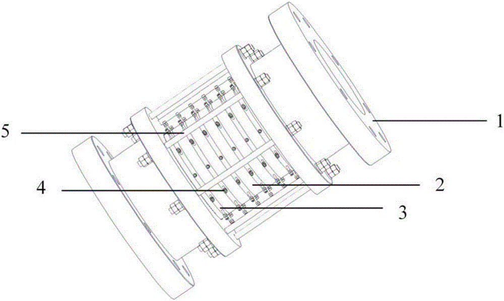
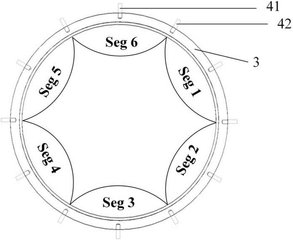
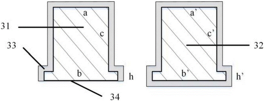
  • Monitoring device and monitoring method for corrosion of inner wall of pipeline
  • Monitoring device and monitoring method for corrosion of inner wall of pipeline
  • Monitoring device and monitoring method for corrosion of inner wall of pipeline

Examples


Embodiment Construction

[0043] In order to make the purpose, technical solutions and advantages of the embodiments of the present invention clearer, the technical solutions in the embodiments of the present invention will be clearly and completely described below in conjunction with the drawings in the embodiments of the present invention. Obviously, the described embodiments It is a part of embodiments of the present invention, but not all embodiments. Based on the embodiments of the present invention, all other embodiments obtained by persons of ordinary skill in the art without creative efforts fall within the protection scope of the present invention.

[0044] The basis of the resistance method for monitoring pipeline corrosion is that corrosion will lead to changes in the resistance value of the electrode, and the corrosion depth can be calculated through the change in resistance value.

[0045] Based on the above design background, the present invention designs a pipeline inner wall corrosion m...


PUM


Abstract

The invention discloses a monitoring device and a monitoring method for corrosion of an inner wall of a pipeline. The device comprises an array annular resistance corrosion sensor, a zero-resistance galvanometer, micro-ohm meters and a signal acquisition control system, wherein the array annular resistance corrosion sensor comprises n corrosion elements and n reference elements; the n corrosion elements and the n reference elements are arranged at intervals through connecting parts; each corrosion element is matched with a relay switch and is coupled through the n micro-ohm meters; the micro-ohm meters are arranged in an external electronic cabin; each annular electrode element is connected to the corresponding micro-ohm meter through the relay switch; the micro-ohm meters are arranged in the external electronic cabin; the signal acquisition control system is used for acquiring and storing measured data of the zero-resistance galvanometer and the micro-ohm meters and controlling the movement of the relay switches. The device disclosed by the invention can be used for accurately monitoring a partial corrosion condition of the pipeline and the defect in the prior art that the partial corrosion monitoring along a pipeline direction cannot be monitored is overcome.

Description

technical field [0001] The invention relates to the technical field of automatic monitoring, in particular to a pipeline inner wall corrosion monitoring device and a monitoring method thereof. Background technique [0002] Oil and gas gathering and transportation is an important part of the development of oil and gas resources. Pipeline transportation has become the main form of oil and gas gathering and transportation due to its advantages of low freight, low energy consumption, large transportation volume, and little impact from the external environment. [0003] There are many uncertain factors affecting pipeline operation. With the increase of pipeline service time, the possibility of pipeline failure gradually increases, and pipeline failure accidents occur from time to time. Among the many factors that lead to pipeline failure, the corrosion of the inner wall of the pipeline is one of the main reasons. Therefore, it is of great significance to grasp the corrosion stat...

Claims


Application Information

Patent Timeline
Patent Type & Authority Applications(China)
IPC IPC(8): G01N17/00
CPCG01N17/00
Inventor 黄一徐云泽贺丽敏王晓娜
Owner DALIAN UNIV OF TECH
Learn More