
Monocular vision based IMU (inertial measurement unit) drift compensation method

A drift compensation, monocular vision technology, applied in instruments, computing, electrical and digital data processing, etc., can solve the problems of IMU error accumulation, inability to apply long-term direction estimation, etc., to achieve the effect of solving long-term error accumulation

Active Publication Date: 2017-05-24
SHENYANG INST OF AUTOMATION - CHINESE ACAD OF SCI
View PDF5 Cites 18 Cited by
  • Summary
  • Abstract
  • Description
  • Claims
  • Application Information

AI Technical Summary

Problems solved by technology

[0004] Aiming at the problem that the current IMU direction estimation has error accumulation and cannot be applied to long-term direction estimation, the present invention proposes an IMU drift compensation method based on monocular vision. In the set of feature point pairs between two adjacent frames of images, external The level line constraint method obtains the vision-based direction estimation value and introduces it into the calibration compensation of the IMU to solve the problem of long-term error accumulation of the IMU

Method used


Image

  • Monocular vision based IMU (inertial measurement unit) drift compensation method
  • Monocular vision based IMU (inertial measurement unit) drift compensation method
  • Monocular vision based IMU (inertial measurement unit) drift compensation method

Examples


Embodiment Construction

[0052] The present invention will be further described in detail below in conjunction with the accompanying drawings and embodiments.

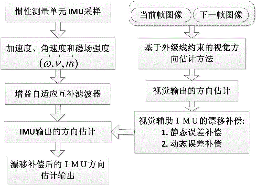
[0053] The inventive method comprises three parts (as figure 1 shown):

[0054] (1) Direction estimation based on IMU;

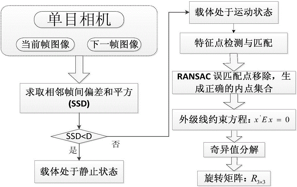
[0055] (2) Direction estimation of the monocular camera;

[0056] (3) Error compensation of the visual aid IMU.

[0057] The specific implementation process is as follows.

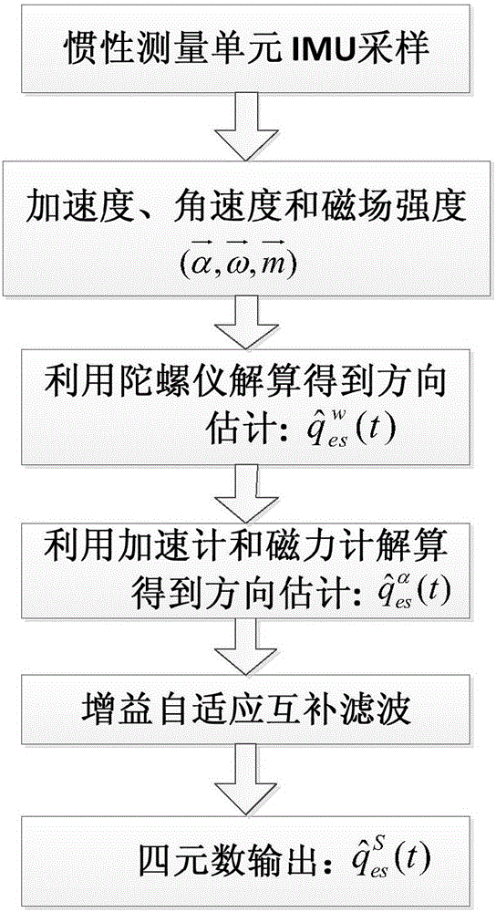
[0058] Step 1: IMU-based orientation estimation (such as figure 2 shown).

[0059] Step 1.1: Compute the orientation estimate for the gyroscope

[0060]

[0061] in Indicates the quaternion estimated by the IMU gyroscope at time t, which consists of (q 0 ,q 1 ,q 2 ,q 3 )express. Among them, the q in the quaternion 1 ,q 2 ,q 3 The components correspond to the projection of the rotation axis in the X, Y, and Z directions, q 0 The component corresponds to the angle at which the IMU rotates around the rotation axis; Indicates the rate ...


PUM


Abstract

The invention provides a monocular vision based IMU (inertial measurement unit) drift compensation method aiming at the problem of failure in application to long-time direction estimation due to error accumulation in direction estimation of an existing IMU. The method includes steps of IMU direction estimation, monocular camera direction estimation and vision assisted IMU error compensation. In a feature point pair set of two adjacent frames of images, a vision-based direction estimation value is obtained according to an epipolar constraint method and led into IMU calibration compensation, so that the problem of IMU long-time error accumulation is solved. The monocular vision based IMU drift compensation method is applicable to static and dynamic error compensation and has advantages of accuracy, stability and zero drift.

Description

technical field [0001] The invention relates to computer vision technology and image processing technology, in particular to an IMU drift compensation method based on monocular vision. Background technique [0002] The Inertial Measurement Unit (IMU) is a MEMS inertial element integrated with a three-axis accelerometer, a three-axis gyroscope, and a three-axis magnetometer, and is used to measure the three-axis angular velocity, three-axis acceleration, and three-axis geomagnetic component of an object. IMU has the characteristics of small size, light weight, portable, easy to wear, etc., and is widely used in carrier direction estimation and motion capture of human joints. [0003] The direction estimation based on IMU has the advantages of small amount of calculation and good dynamic characteristics, and is suitable for direction estimation in a short time. However, due to the accumulation of errors caused by the drift of the MEMS sensor itself, it is difficult for the IM...

Claims


Application Information

Patent Timeline
Patent Type & Authority Applications(China)
IPC IPC(8): G06F19/00
Inventor 梁炜张吟龙谈金东张晓玲李杨
Owner SHENYANG INST OF AUTOMATION - CHINESE ACAD OF SCI
Learn More