
Resin piping with flow aids

A technology of auxiliary parts and pipes, which is applied in the field of resin pipes, can solve the problems of weak materials of flow auxiliary parts and cannot be supported by resin pipes, etc., and achieve the effect of rapid cost

Active Publication Date: 2019-10-11
FASERVERBUND INNOVATIONS UG HAFTUNGSBESCHRANKT
View PDF1 Cites 0 Cited by
  • Summary
  • Abstract
  • Description
  • Claims
  • Application Information

AI Technical Summary

Problems solved by technology

But the flow aid material that makes up the tabs is too weak to support the resin tubing firmly enough against the laminate

Method used


Image

  • Resin piping with flow aids

Examples


Embodiment Construction

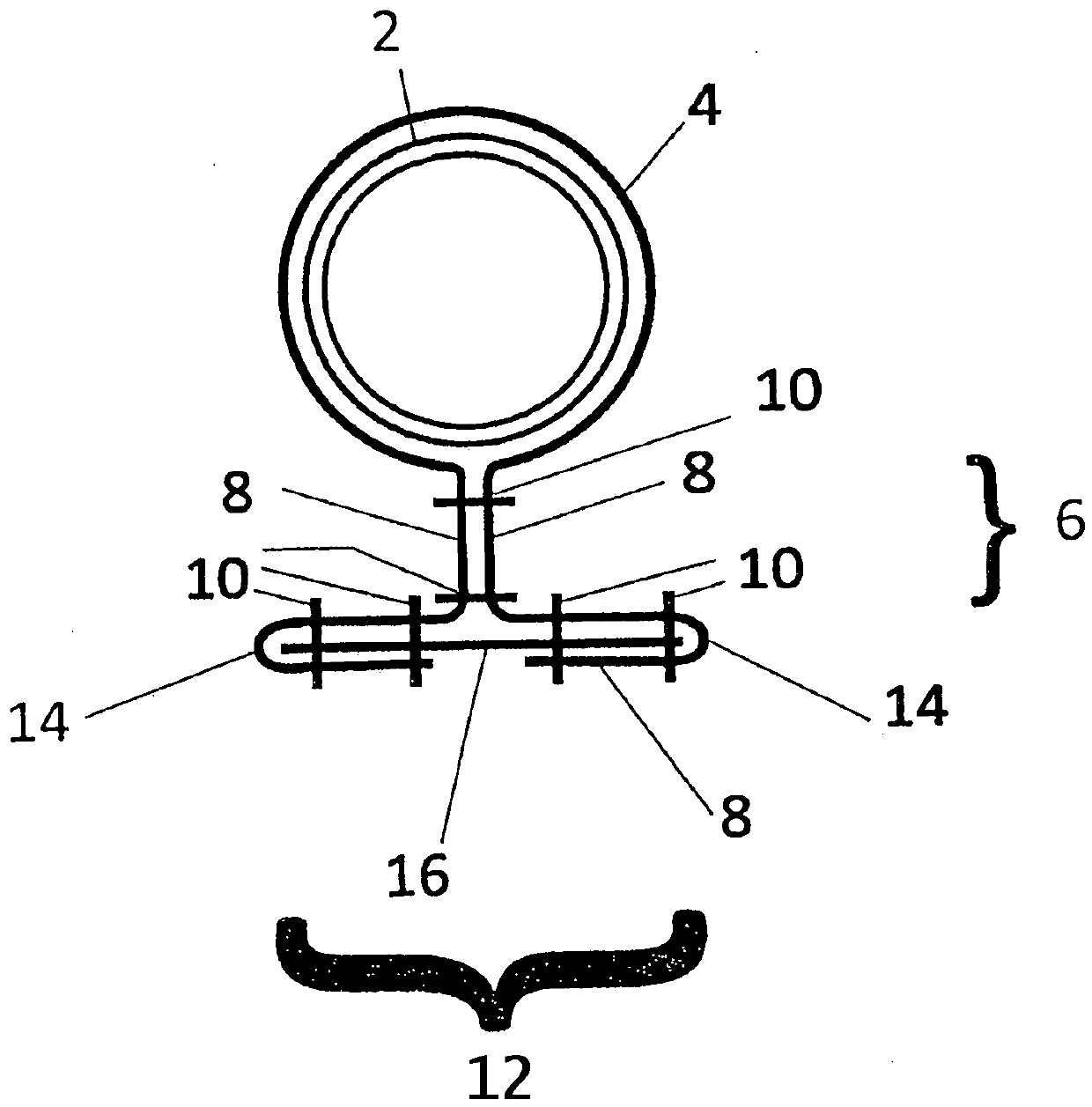
[0018] The present invention will now be described in more detail based on examples. The drawing shows a resin line 2 through which the matrix material is guided. The matrix material can penetrate from the inside of the resin line 2 to the outside through openings not further shown in the drawing. There, the matrix material comes into contact with the flow aid material 4 , which is arranged as a jacket around the resin line 2 .

[0019] The flow aid material 4 is dimensioned such that the tab 8 projects beyond the circumference of the resin line 2 beyond the circumference of the resin line 2 and forms a double-layer web 6 in a section. The two protruding tabs 8 of the flow aid material 4 are connected to one another in the region of the web 6 by the two shown stitched seams 10 .

[0020] At the end of the web 6 facing away from the resin line 2 there is a section 12 bent relative to the web. In the present embodiment, the bent section 12 comprises two rings 14 into which th...


PUM


Abstract

The invention relates to a resin pipe (2) comprising an opening on a circumferential side and a sleeve made of flow aid material (4). In order to design the resin line in such a way that it does not leave marks on the surface of the component under the influence of the vacuum and to improve the resin output, it is proposed that the flow aid material (4) is arranged around the resin line (2) in such a way that the flow aid material The lugs (8) of (4) that protrude from the resin pipe (2) form a double-layer tab (6), in the area of ​​which the tabs (8) are connected to each other, and in the area of ​​the tab (6) ) on the end facing away from the resin pipe (2) is adjacent to the segment (12) bent relative to the tab, wherein one or two tabs (8) are adjacent to the segment of the tab (6) Arranged in one or two rings (14) which form the bent section (12).

Description

technical field [0001] The invention relates to a resin pipe comprising an opening on a circumferential side and a sleeve made of a flow aid material. Background technique [0002] From the prior art, resin lines are known which are used in vacuum infusion methods in order thereby to introduce matrix material into a hermetically closed infusion mold. In order to facilitate the ejection of the matrix material from the resin pipes and its penetration and diffusion in the infusion mold, the resin pipes are surrounded by flow aids. However, when using resin pipes, it has been found to be disadvantageous that the shape of the resin pipes appears as traces in the surface of the produced laminate, since the sealing film sucks the resin pipes onto the component by vacuum. Furthermore, the contact surface of the resin line with the flow aid facing the interior of the mold, through which matrix material can enter the interior of the mold, is less exposed to the vacuum. As a result, ...

Claims


Application Information

Patent Timeline
Patent Type & Authority Patents(China)
IPC IPC(8): B29C70/44B29C70/54
CPCB29C70/443B29C70/548
Inventor D·迪克斯
Owner FASERVERBUND INNOVATIONS UG HAFTUNGSBESCHRANKT
Learn More