Universal locating clamp

A positioning fixture, a universal technology, applied in the direction of manufacturing tools, workpiece clamping devices, etc., can solve problems such as difficult to popularize and use, long operating hours, long alignment process, etc.

Active Publication Date: 2017-05-31
东莞市优米佳自动化设备有限公司
10 Cites 0 Cited by

AI-Extracted Technical Summary

Problems solved by technology

The second is the universal positioning fixture commonly used in the market. This kind of universal positioning fixture needs to be aligned manually, and then put into the laminating machine for lamination after manual pressing. The air...

Method used

[0027] In the present embodiment, the first parallelogram linkage mechanism 21 and the second parallelogram linkage mechanism 22 are all composed of four connecting rods pivotally connected head to tail. Both the first parallelogram linkage mechanism 21 and the second parallelogram linkage mecha...

Abstract

The invention discloses a universal locating clamp comprising a clamp seat and a connecting rod locating mechanism connected with the clamp seat in a pivoted manner. The connecting rod locating mechanism comprises two first parallelogram linkage mechanisms symmetrically arranged on the two sides of the Y-axis of the clamp seat, two second parallelogram linkage mechanisms symmetrically arranged on the two sides of the X-axis of the clamp seat and a plurality of locating connecting rods, wherein a part of the locating connecting rods are transversely arranged between the two first parallelogram linkage mechanisms, the other locating connecting rods are longitudinally arranged between the two second parallelogram linkage mechanisms, and the locating connecting rods are used for forming a workpiece locating frame. When the first parallelogram linkage mechanisms and the second parallelogram linkage mechanisms rotate reversely around pivoted shafts, a workpiece is clamped by the workpiece locating frame. When the first parallelogram linkage mechanisms and the second parallelogram linkage mechanisms rotate forwards around the pivoted shafts, the workpiece is separated from the workpiece locating frame. By the adoption of the structural design, the universal locating clamp locates the workpiece accurately and is convenient to operate and high in universality.

Application Domain

Work holders

Technology Topic

EngineeringLinkage concept +2

Image

  • Universal locating clamp
  • Universal locating clamp
  • Universal locating clamp

Examples

  • Experimental program(1)

Example Embodiment

[0024] The technical solutions of the present invention will be further described below in conjunction with the drawings and specific implementations.
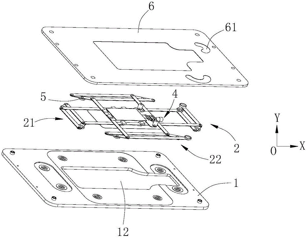
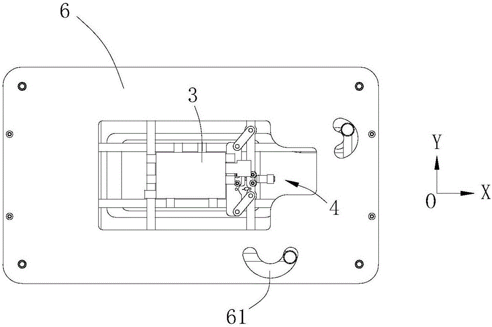
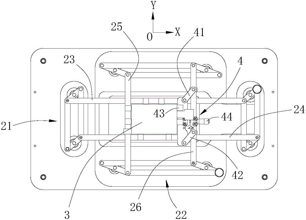
[0025] Such as Figure 1 to Figure 5 As shown, a universal positioning fixture in this embodiment includes a fixture base 1, and a link positioning mechanism 2 pivotally connected to the fixture base 1. The linkage positioning mechanism 2 includes Y symmetrically arranged on the fixture base 1. Two first parallelogram link mechanisms 21 on both sides of the shaft, two second parallelogram link mechanisms 22 symmetrically arranged on both sides of the X-axis of the clamp base 1, and two first parallelogram links transversely arranged A number of positioning links used to form a workpiece positioning frame between the connecting rod mechanisms 21 and longitudinally arranged between the two second parallelogram connecting rod mechanisms 22;
[0026] Specifically, the several positioning links in this embodiment include a first X-axis link 23 and a second X-axis link 24 that are arranged in parallel between the adjacent first parallelogram link mechanisms 21, and The first Y-axis link 25 and the second Y-axis link 26 are arranged in parallel between the adjacent second parallelogram link mechanisms 22. The first X-axis link 23 and the second X-axis link 24 slide vertically and horizontally with the first Y-axis link 25 and the second Y-axis link 26 to form image 3 and Figure 4 The workpiece positioning frame shown is driven by the first parallelogram linkage mechanism 21 and the second parallelogram linkage mechanism 22 so that the workpiece positioning frame can contract inward or expand outward, thereby facilitating positioning of the workpiece .
[0027] In this embodiment, the first parallelogram linkage mechanism 21 and the second parallelogram linkage mechanism 22 are both formed by pivoting and combining four linkage rods in turn. The pivotal joints between the first parallelogram linkage mechanism 21 and the second parallelogram linkage mechanism 22 and the clamp base 1 are both provided with powerful magnets 5. In this way, the magnetic force generated by the powerful magnet can be used to enable the first parallelogram linkage mechanism 21 and the second parallelogram linkage mechanism 22 to accurately move and position.
[0028] In this embodiment, both ends of the first X-axis link 23 and the second X-axis link 24, and the first Y-axis link 25 and the second Y-axis link 26 are between the adjacent links. The pivot shaft is pivoted to form a linkage. In order to facilitate the positioning of workpieces of different sizes, the first X-axis link 23, the second X-axis link 24, and the first Y-axis link 25 in this embodiment The three connecting rods are all provided with positioning sliders.
[0029] In order to facilitate the fine adjustment of the position of the workpiece after positioning, a fine adjustment mechanism 4 for fine adjustment is provided on the second Y-axis connecting rod 26 in this embodiment. The fine adjustment mechanism 4 includes a first link 41 and a second link 42 pivotally connected to the positioning link in parallel and spaced apart, and both ends are pivotally connected to the first link 41 and the second link 42 and are connected to the positioning link. The positioning plate 43 is arranged in parallel with the positioning link, and the screw rod 44 is used to drive the positioning plate 43 to move back and forth along the X axis or the Y axis. In this way, the second adjustment of the workpiece position can be carried out conveniently and effectively.
[0030] In this embodiment, the clamp base 1 under the workpiece positioning frame is provided with a hole 12 for the workpiece 3 to fit the external workpiece 3 through.
[0031] The universal positioning fixture further includes a top cover 6 that is matched with the clamp base 1 to form a cavity for accommodating the connecting rod positioning mechanism 2, and the top cover 6 is provided with a driving chute 61 through it. When in use, the power output end of the external drive device can be pivotally connected to the connecting rod in the chute and slide along the arc-shaped drive chute, thereby converting the arc-shaped motion trajectory into the connection in the X and Y axis directions. The linear movement of the rod facilitates and effectively clamps or releases the workpiece.
[0032] The technical principle of the present invention has been described above in conjunction with specific embodiments. These descriptions are only for explaining the principle of the present invention, and cannot be construed as limiting the protection scope of the present invention in any way. Based on the explanation here, those skilled in the art can think of other specific embodiments of the present invention without creative work, and these methods will fall within the protection scope of the present invention.

PUM

no PUM

Description & Claims & Application Information

We can also present the details of the Description, Claims and Application information to help users get a comprehensive understanding of the technical details of the patent, such as background art, summary of invention, brief description of drawings, description of embodiments, and other original content. On the other hand, users can also determine the specific scope of protection of the technology through the list of claims; as well as understand the changes in the life cycle of the technology with the presentation of the patent timeline. Login to view more.
Why Eureka
Try Eureka