
Die lifting device

A mold and guide rod technology, applied in the field of fitter tools, can solve problems such as inconvenient operation, heavy quality, and large volume

Inactive Publication Date: 2017-05-31
GUANGDONG EVERWIN PRECISION TECH
View PDF6 Cites 0 Cited by
  • Summary
  • Abstract
  • Description
  • Claims
  • Application Information

AI Technical Summary

Problems solved by technology

The C-shaped clip is large in size and heavy in weight, and it is inconvenient to operate.

Method used


Image

  • Die lifting device
  • Die lifting device

Examples


Embodiment Construction

[0021] In order to facilitate the understanding of the present invention, the present invention will be described more fully below with reference to the relevant drawings. The preferred embodiments of the present invention are shown in the drawings. However, the present invention can be implemented in many different forms and is not limited to the embodiments described herein. On the contrary, the purpose of providing these embodiments is to make the disclosure of the present invention more thorough and comprehensive.

[0022] It should be noted that when an element is considered to be "connected" to another element, it may be directly connected to the other element or a centered element may exist at the same time. The terms "vertical", "horizontal", "left", "right" and similar expressions used herein are for illustrative purposes only, and are not meant to be the only embodiments.

[0023] Unless otherwise defined, all technical and scientific terms used herein have the same mea...


PUM


Abstract

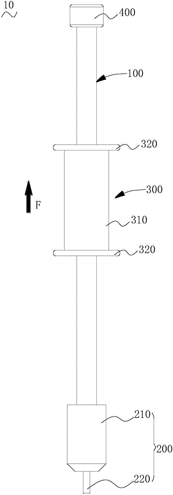
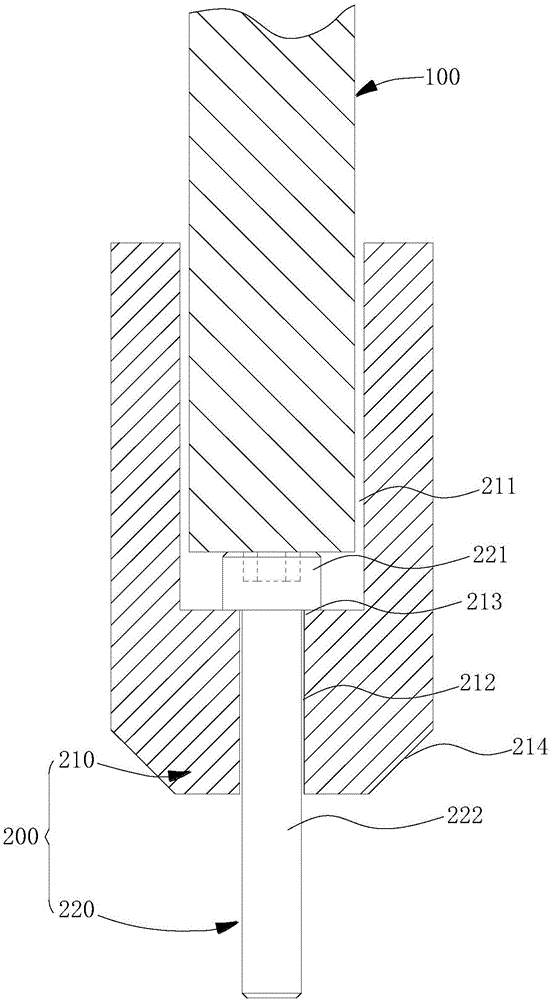
The invention relates to a die lifting device used for lifting out a workpiece to be subject to die lifting from a formwork. The die lifting device comprises a guide rod, a die lifting connector and a die lifting pulling head, the back end of the guide rod is provided with a positioning head, the die lifting connector comprises a connector detachably connected to the front end of the guide rod and a screw connected with the connector and used for being fastening connection with the workpiece to be subject to die lifting, and the die lifting pulling head is movably arranged on the guide rod in a sleeving manner and can slide between the positioning head and the connector along the guide rod. According to the die lifting device, the guide rod rotates to drive the screw of the die lifting connector to screw the screw into the workpiece to be subject to die lifting, force is exerted to pull the die lifting pulling head to the back end to enable the back end of the guide rod to be collided with the positioning head, then the workpiece to be subject to die lifting can be lifted out from the formwork, use is convenient, and the die lifting efficiency is high; and in addition, the die lifting connector is detachably connected to the guide rod, only matched die lifting connectors need to be replaced according to different workpieces to be subject to die lifting, the overall set of die lifting device does not need to be customized, the production cost can be greatly saved, and the applicability of the die lifting device is wide.

Description

Technical field [0001] The invention relates to the field of fitter tools, in particular to a puller. Background technique [0002] In fitter production, it is often necessary to pull out the positioning screws and positioning pins that are fastened in the mold when disassembling the mold, and the positioning screws and positioning pins are tightly integrated in the mold and are not easy to pull out. The existing method is to knock out the positioning screws and positioning pins from the template, or to open internal threaded holes on the positioning screws and positioning pins, and then use another threaded rod to fasten the threads of the internal threaded holes, and pull them manually The threaded rod pulls out the positioning screw and positioning pin. This manual operation method is laborious, slow in mold removal, and low in efficiency. [0003] In addition, during the drafting process, it is necessary to use auxiliary tools such as C-clamps to lock the thimble plate and th...

Claims


Application Information

Patent Timeline
Patent Type & Authority Applications(China)
IPC IPC(8): B25B27/00
CPCB25B27/00
Inventor 奉继法陈冰锋韩升一
Owner GUANGDONG EVERWIN PRECISION TECH
Learn More