Circulating reciprocate lifting mechanism

A reciprocating and troughing technology, applied in the direction of hoisting device, hoisting device, etc., can solve the problems of high equipment cost, low transportation efficiency, large loss of power and energy consumption, etc., and achieve high space utilization, improve transportation efficiency, transportation low cost effect

Active Publication Date: 2017-05-31
SF TECH
View PDF6 Cites 0 Cited by
  • Summary
  • Abstract
  • Description
  • Claims
  • Application Information

AI Technical Summary

Problems solved by technology

[0003] Warehouse configuration and distribution centers in the logistics industry often need to transport goods from low places to high places during the transportation of goods. Due to the limited width of the transmission channel, the structure of traditional transmission equipment is complex, difficult to maintain, and the loss of power energy consumption is large. The efficiency of goods entering and leaving the warehouse Low, directly resulting in high equipment costs, increasing the cost of transportation in the logistics and transportation industry, and the manual operation is unstable, and the transportation efficiency is low. It is not suitable for the current one-stop solution for express delivery.

Method used


Image

  • Circulating reciprocate lifting mechanism
  • Circulating reciprocate lifting mechanism
  • Circulating reciprocate lifting mechanism

Examples


Embodiment Construction

[0022] The application will be further described in detail below in conjunction with the accompanying drawings and embodiments. It should be understood that the specific embodiments described here are only used to explain related inventions, rather than to limit the invention. It should also be noted that, for ease of description, only parts related to the invention are shown in the drawings.

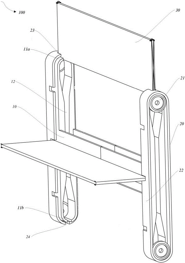
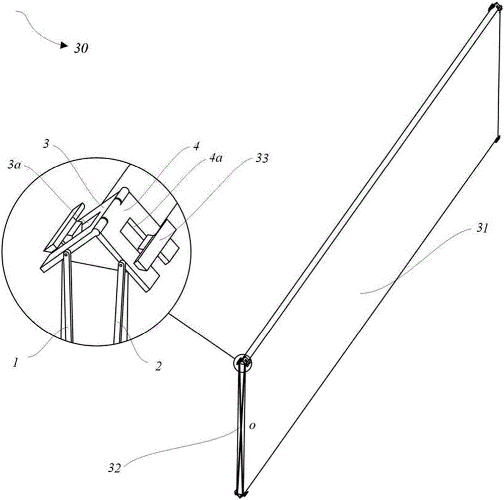
[0023] figure 1 It is a structural schematic diagram of a reciprocating lifting mechanism according to an embodiment of the present invention. As shown in the figure, the reciprocating lifting mechanism 100 includes: a support frame 10 , a pair of conveying devices 20 and a loading board 30 .

[0024] The support frame 10 has a vertical slot 12, and the two ends of the slot 12 include an inlet and an outlet. The supporting frame 10 can be fixed on the ground or any movable equipment.

[0025] A pair of conveying devices 20 are arranged around two sides of the outer contour of the su...


PUM


Abstract

The invention discloses a circulating reciprocate lifting mechanism. The circulating reciprocate lifting mechanism comprises a supporting frame, a pair of conveying devices and loading plates. Vertical through grooves are formed in the supporting frame, and the two ends of each through groove comprises an inlet and an outlet correspondingly. The conveying devices are arranged on the two sides of the outer side outline of the supporting frame in a surrounding mode, and at least one pair of clamping grooves which correspond to the inlet and the outlet of the corresponding groove correspondingly are formed in each conveying device. One end of each loading plate is clamped in one corresponding clamp groove of the pair conveying devices, wherein the loading plates are lifted to the positions over the supporting frame with movement of the conveying devices, when the loading plates aligns with inlets of the through grooves, the conveying devices stop, and the loading plates fall down along the through holes under the effect of gravity of the loading plates and stretch out of the outlets; and the other end of each loading plate is clamped in the corresponding other clamping groove of the pair conveying devices, and thus the loading plates are lifted with movement of the conveying devices in a circulating and reciprocating mode. According to the circulating reciprocate lifting mechanism, an intermittent movement device is adopted by the mechanism to achieve circulating and reciprocating of lifting action of goods, the structure is compact, the space utilization ratio is high, and conveying efficiency of the goods is improved.

Description

technical field [0001] The invention relates to the field of logistics transportation equipment, in particular to a reciprocating lifting mechanism for transporting goods. Background technique [0002] With the widespread popularity of e-commerce and online shopping, the postal logistics industry is developing rapidly, and express parcels are also increasing. How to realize unmanned logistics solutions integrating receiving, sorting, storage, and distribution has become an important goal for the development of logistics companies. [0003] Warehouse configuration and distribution centers in the logistics industry often need to transport goods from low places to high places during the transportation of goods. Due to the limited width of the transmission channel, the structure of traditional transmission equipment is complex, difficult to maintain, and the loss of power energy consumption is large. The efficiency of goods entering and leaving the warehouse Low, directly result...

Claims


Application Information

Patent Timeline
IPC IPC(8): B66F19/00
CPCB66F19/00
Inventor 雷鹏涛
Owner SF TECH
Why Eureka
Try Eureka