Tube segment shipping and trolley towing integrated device of shield machine

A technology of shield machine and segment assembling machine, which is applied in transportation and packaging, cranes, shaft equipment, etc., can solve the problems of increased labor intensity of staff, increased equipment failure rate, reduced transportation efficiency, etc., so as to reduce the labor intensity of workers , The effect of reducing equipment cost and high transportation efficiency

Inactive Publication Date: 2012-03-21
BEIJING SANY HEAVY MASCH CO LTD
7 Cites 30 Cited by

AI-Extracted Technical Summary

Problems solved by technology

Since the lifting device adopts a two-section double-beam structure to transport the segment, after the segment 5' is transported on the main double-track beam 1', it needs to be unloaded from the electric hoist 3' of the beam and then installed on the auxiliary double-track beam 2' O...

Abstract

The invention relates to a tube segment shipping and trolley towing integrated device of a shield machine, belonging to the technical field of tunneling equipment. The integrated device comprises a two-track beam, a pair of electric hoists mounted under the two-track beam, a travelling trolley towing the electric hoists to travel and a connecting frame; the connecting frame is mounted on the two-track beam; the two-track beam is mounted between a traveling beam of a tube segment assembling machine and a first-section trolley of a back affiliated system; the front-station working end and the back-station working end of the two-track beam are horizontal beams, and a middle part of the two-track beam is an tilted beam; the front end of the two-track beam is lower than the back end of the two-track beam; the connecting frame is a truss structure; the left side and the right side of the connecting frame are respectively connected with the two beams of the two-track beam; the front end of the connecting frame is movably connected with the traveling beam of the tube segment assembling machine; and the back end of the connecting frame is connected with the first-section trolley of the back affiliated system through a pin shaft. The tube segment shipping and trolley towing integrated device of the shield machine provided by the invention has a simple structure, the bearing strength is enhanced under the premise of not increasing the weight, the shipping efficiency is high, the labor intensity for workers is lowered, and the cost and the failure rate of equipment are lowered.

Application Domain

Technology Topic

Image

  • Tube segment shipping and trolley towing integrated device of shield machine
  • Tube segment shipping and trolley towing integrated device of shield machine
  • Tube segment shipping and trolley towing integrated device of shield machine

Examples

  • Experimental program(1)

Example Embodiment

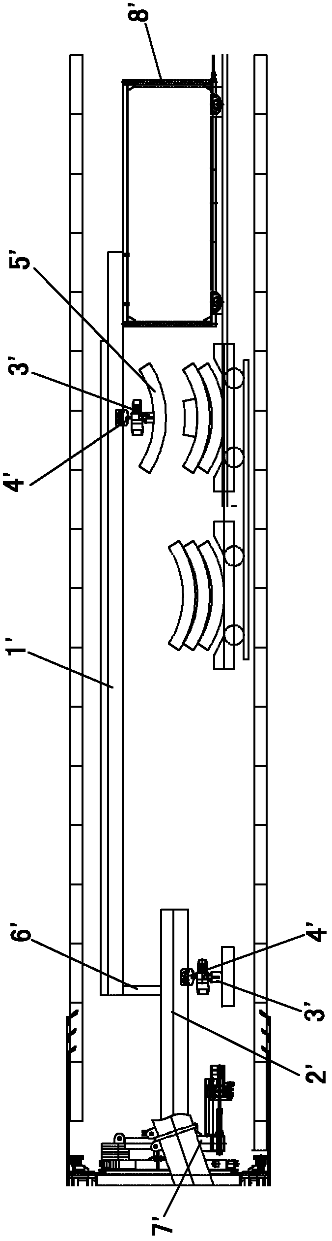
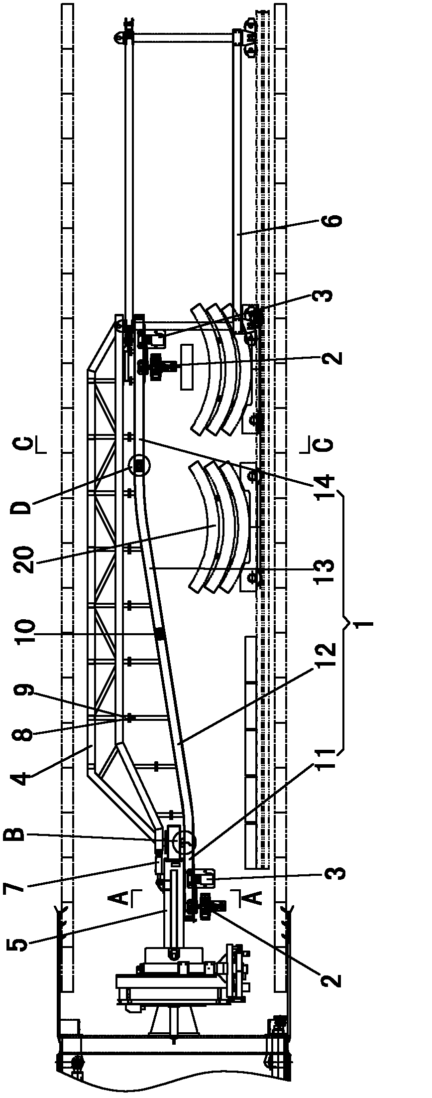
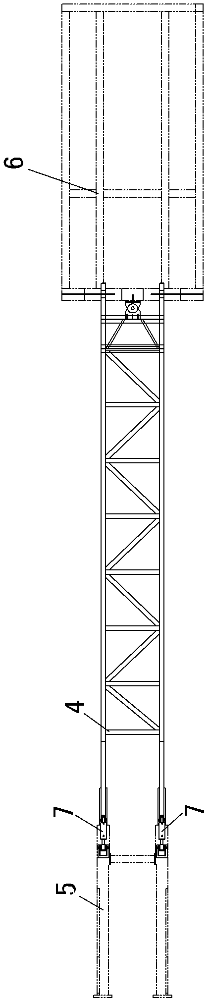
[0021] like figure 2 , image 3 and Image 6 As shown, the integrated device for segment hoisting and trolley traction of the shield tunneling machine of the present invention includes a double-rail beam 1, a pair of electric hoists 2 hoisted under the double-rail beam 1, a walking trolley 3 for pulling the electric hoist 2, and a connecting frame 4 , the double-track beam 1 is installed between the traveling beam 5 of the segment assembly machine and the supporting first trolley 6 in the rear.
[0022] combine figure 2 As shown, the double-track beam 1 is an I-beam, the front and rear ends of the double-track beam 1 are horizontal beams, and the middle part is an inclined beam. The inclined middle front beam 12, the inclined middle rear beam 13 whose front end height is smaller than the rear end height, and the horizontal rear beam 14 are connected end to end. The double-track beam 1 is composed of multi-section beam connections, which facilitates the transportation of the double-track beam, and can be installed in the shield shell at any time along with the shield machine at the work site.
[0023] combine Figure 4 As shown, hanging lugs 51 are connected to the bottom surface of the traveling beam 5 of the segment assembly machine, and the front end of the front beam 11 is hung on the hanging lugs 51 .
[0024] combine figure 2 and Figure 5 As shown, the joint surfaces of the front beam 11 and the middle front beam 12 are respectively processed with a first connecting ear 111 and a second connecting ear 121, the first connecting ear 111 and the second connecting ear 121 are connected by a pin, and the first connecting ear 111 There is a movable gap between the second connecting ear 121, so that when the shield machine is turning, it can be ensured that the front beam 11 can rotate in a small arc relative to the middle front beam 12, which will not affect the turning of the shield machine.
[0025] combine figure 2 As shown, the rear end of the middle front beam 12 and the front end of the middle rear beam 13 are fixedly connected together by two plane splints 10 and several bolts.
[0026] combine figure 2 , Figure 7 and Figure 8 As shown, the rear end of the middle rear beam 13 and the front end of the rear beam 14 are fixedly connected together by two plane splints 10 and several bolts, and the rear end of the rear beam 14 is fixed on the supporting first joint trolley 6 in the back.
[0027] combine figure 2 As shown, the connecting frame 4 is a truss structure, the connecting frame 4 is installed on the top of the double-track beam 1, and the left and right sides of the connecting frame 4 are respectively connected with the two beams of the double-track beam 1. The upper surface of the double-track beam 1 is vertically welded with several first connecting columns 8, and the lower surface of the connecting frame 4 is vertically welded with several second connecting columns 9, and the positions of the first connecting columns 8 and the second connecting columns 9 correspond to each other up and down. , the first connecting column 8 and the second connecting column 9 are fixed by bolt connection. The connection between the double-track beam 1 and the connecting frame 4 is convenient for installation and simple in structure. The left and right sides of the front end of the connecting frame 4 are respectively connected with the bottom rear ends of the two hydraulic cylinders 7 through pins, and the piston rods at the front ends of the two hydraulic cylinders 7 are respectively connected with the segment assembly machine walking beam 5 through pins. In this way, when the shield machine is turning, it is ensured that the connecting frame 4 can rotate in the horizontal plane relative to the segment assembly machine walking beam 5, without affecting the turning and walking of the shield machine. The rear end of connecting frame 4 is connected by bearing pin with supporting first joint trolley 6 in the back.
[0028] When in use, hoist the segments 20 placed on the first supporting trolley 6 on the two electric hoists 2, and the electric hoists 2 run forward from the rear end of the rear beam 14 through the center under the traction of the trolley 3. The rear beam 13, the middle front beam 12 to the front end of the front beam 11, below the front beam 11 is the segment assembly machine, the segment 20 is unloaded, and the segment 20 is grabbed by the grabbing device on the segment assembly machine, and the electric hoist 2. Return to the rear end of the rear beam 14 under the traction of the walking trolley 3, and repeat the above operations.
[0029] The integrated device for segment hoisting and trolley traction of the shield tunneling machine of the present invention realizes the transmission of the electric hoist 2 through a double-track beam 1 installed between the segment assembly machine walking beam 5 and the supporting first trolley 6, so that Under the traction of the trolley 3, the electric hoist 2 runs from the rear end of the rear beam 14 of the double-track beam 1 to the front end of the front beam 11 of the double-track beam 1, and directly transports the segment 20 suspended under the electric hoist 2 to the segment assembly machine. Its transportation efficiency is high, and the labor intensity of workers is reduced, and the transportation process only needs a pair of electric hoists 2 to hang the segment 20, which can reduce the equipment cost, and at the same time, the reduction of equipment can reduce the failure rate of the equipment. The truss structure connecting frame 4 installed above can increase the bearing strength of the double-track beam 1 without increasing the weight of the double-track beam 1, and the device has a simple structure.
[0030] The above-mentioned embodiments are only descriptions of the preferred implementation modes of the present invention, and are not intended to limit the scope of the present invention. Variations and improvements should fall within the scope of protection defined by the claims of the present invention.

PUM

no PUM

Description & Claims & Application Information

We can also present the details of the Description, Claims and Application information to help users get a comprehensive understanding of the technical details of the patent, such as background art, summary of invention, brief description of drawings, description of embodiments, and other original content. On the other hand, users can also determine the specific scope of protection of the technology through the list of claims; as well as understand the changes in the life cycle of the technology with the presentation of the patent timeline. Login to view more.

Similar technology patents

Liquefied oxygen transport ship

InactiveCN102815375AImprove transportation efficiencyReduce shipping costsFor bulk goodsOxygen transportLiquid oxygen
Owner:CHINA GEZHOUBA GROUP MACHINERY & SHIP +2

Dumping unit of pipeline transporter

ActiveCN104553949ALow costImprove transportation efficiencyVehicle to carry long loadsLoading/unloading vehicle arrangmentTerrainPipeline transport
Owner:HUNAN JIANGLU SPECIAL EQUIP

Classification and recommendation of technical efficacy words

  • Improve transportation efficiency
  • Reduce manual labor intensity

Movable type shield launching device for narrow and small space

PendingCN107575239AHave working conditionsImprove transportation efficiencyTunnelsMovable typeBuilding construction
Owner:YSD RAIL TRANSIT CONSTR CO LTD
Why Eureka
Try Eureka