A bushing buckling-inducing brace with hybrid concave-type inducing units

A sunken casing technology, which is applied in the field of buckling-induced casing steel structure or concrete structure, can solve the problems that are not conducive to the generation of plastic hinges, weaken the energy dissipation capacity of the support, and have little design flexibility, so as to reduce the humidity Work workload, flexible layout, and the effect of ensuring the quality of components

Active Publication Date: 2019-04-12
SOUTHEAST UNIV
View PDF4 Cites 2 Cited by
  • Summary
  • Abstract
  • Description
  • Claims
  • Application Information

AI Technical Summary

Problems solved by technology

On June 1, 2016, the applicant proposed an energy-dissipative buckling-constrained support with symmetrical initial defect units at the end (application number 201610383430.5) and a buckling-controlled support with diamond-shaped energy-dissipating units at the end (application No. 201610380804.8) has a fixed geometric configuration and little design flexibility
Moreover, the thickness and structure of the energy-dissipating unit at the crease in the above support are the same as those at the non-crease, which is not conducive to the generation of plastic hinges at the crease.
In addition, these supports are composed of end restraint segments, buckling segments, and sleeves. The sleeves are on the outside of the buckling segment, and there is no support on the inside of the buckling segment, which is prone to low-order instability toward the inside, thereby weakening the energy dissipation capacity of the support.

Method used


Image

  • A bushing buckling-inducing brace with hybrid concave-type inducing units
  • A bushing buckling-inducing brace with hybrid concave-type inducing units
  • A bushing buckling-inducing brace with hybrid concave-type inducing units

Examples


Embodiment Construction

[0029] The present invention will be further described below in conjunction with the accompanying drawings.

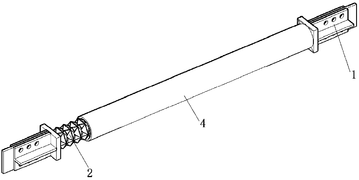
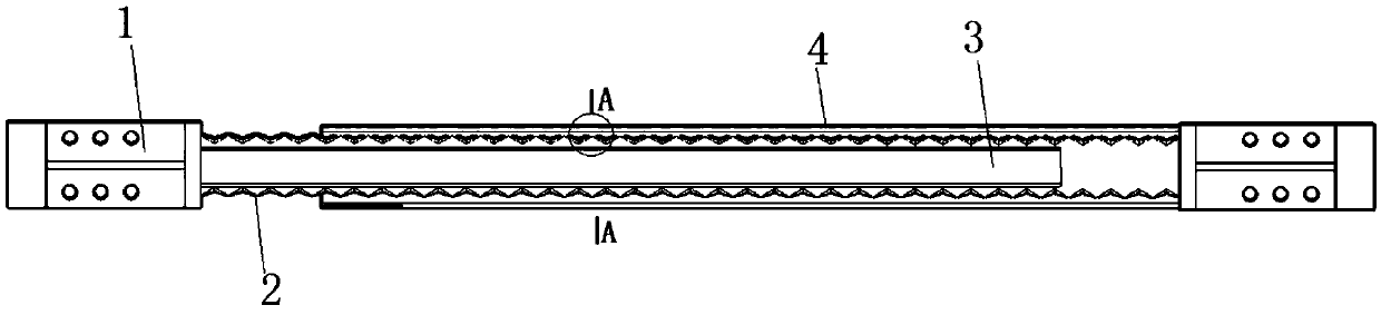
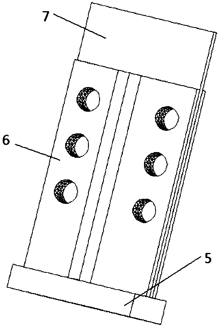
[0030] Such as figure 1 , 2 As shown, it consists of an end restraint section 1, a buckling induction section 2, an inner sleeve 3 and an outer sleeve 4. The end constraining section 1 is fixed at both ends of the buckling inducing section 2 . The left end of the inner sleeve is welded to the square steel plate 5 of the left end restraint section 1, and there is a distance between the right end of the inner sleeve and the square steel plate of the right end restraint section, which is not less than 1 / 40 of the length of the buckling induction section ; The right end of the outer sleeve is welded to the square steel plate 5 of the right end restraint section 1, and there is a distance between the left end of the outer sleeve and the square steel plate of the left end restraint section, and the distance is no less than 1 / 40 of the length of the buckling induction secti...


PUM


Abstract

The invention discloses a casing buckling induction brace with a mixed sunken type induction unit. The casing buckling induction brace comprises end restrained sections, a buckling induction section, an inner casing and an outer casing. The buckling induction section is clamped between the inner casing and the outer casing. The inner casing and the outer casing are each connected with one end restrained section. The buckling induction section comprises at least one mixed sunken type induction unit in the axial direction of the brace. According to each single mixed sunken type induction unit, m same mixed sunken type subunits are arranged sequentially in the circumferential direction to form a space body with the section of an m-edge shape. Each mixed sunken type subunit is a space body formed by folding two trapezoidal plates and eight triangular plates which are located in the same plane. The casing buckling induction brace maintains elasticity under the action of a small earthquake, the buckling induction section enters a yield stage under the action of a medium earthquake or a large earthquake, and the good hysteretic energy consumption performance of the casing buckling induction brace can also achieves an effect of a damper.

Description

technical field [0001] The invention belongs to the technical field of building structures, and in particular relates to a casing buckling-inducing support with mixed concave-type inducing units, which is suitable for steel structures or concrete structures with buckling-constrained supports. Background technique [0002] During the use of steel structures or reinforced concrete structures, ordinary supports will buckle under compression. When the supports buckle under compression, the stiffness and bearing capacity will decrease sharply. Under the action of earthquake or wind, the internal force of the support changes back and forth under the two states of compression and tension. When the support gradually changes from the buckling state to the tension state, the internal force and stiffness of the support are close to zero. Therefore, the hysteretic performance of ordinary supports is poor under repeated loads. In order to solve the problem of buckling under compression...

Claims


Application Information

Patent Timeline
Patent Type & Authority Patents(China)
IPC IPC(8): E04B1/98
CPCE04H9/021
Inventor 蔡建国冯健周宇航吴胜平柳杨青
Owner SOUTHEAST UNIV
Why Eureka
Try Eureka