
Real-time automatic monitoring system and method for acoustic, electric and gas in coal-rock dynamic disasters

An automatic monitoring and dynamic disaster technology, which is applied in the direction of earth drilling, mining equipment, mining equipment, etc., can solve the problems of low detection and identification accuracy, poor real-time performance, and great impact on safe and efficient production, so as to improve the degree of automation and early warning Accuracy, the effect of ensuring synchronization

Active Publication Date: 2018-08-21
CHINA UNIV OF MINING & TECH
View PDF5 Cites 0 Cited by
  • Summary
  • Abstract
  • Description
  • Claims
  • Application Information

AI Technical Summary

Problems solved by technology

[0009] In addition, the abnormal area in front of the working face has a great impact on safe and efficient production. It is the main area where coal-rock gas dynamic disasters occur. However, the accuracy of detection and recognition is low for small and less abnormal areas, which has a great impact on mining activities and poor real-time performance. How to use monitoring methods to effectively monitor and identify structures, high stress, coal thickness changes, Changes in the strength of coal and rock mass and abnormal gas occurrence are also issues that need to be resolved urgently

Method used


Image

  • Real-time automatic monitoring system and method for acoustic, electric and gas in coal-rock dynamic disasters
  • Real-time automatic monitoring system and method for acoustic, electric and gas in coal-rock dynamic disasters
  • Real-time automatic monitoring system and method for acoustic, electric and gas in coal-rock dynamic disasters

Examples


Embodiment Construction

[0021] An example of the present invention will be further described below in conjunction with accompanying drawing:

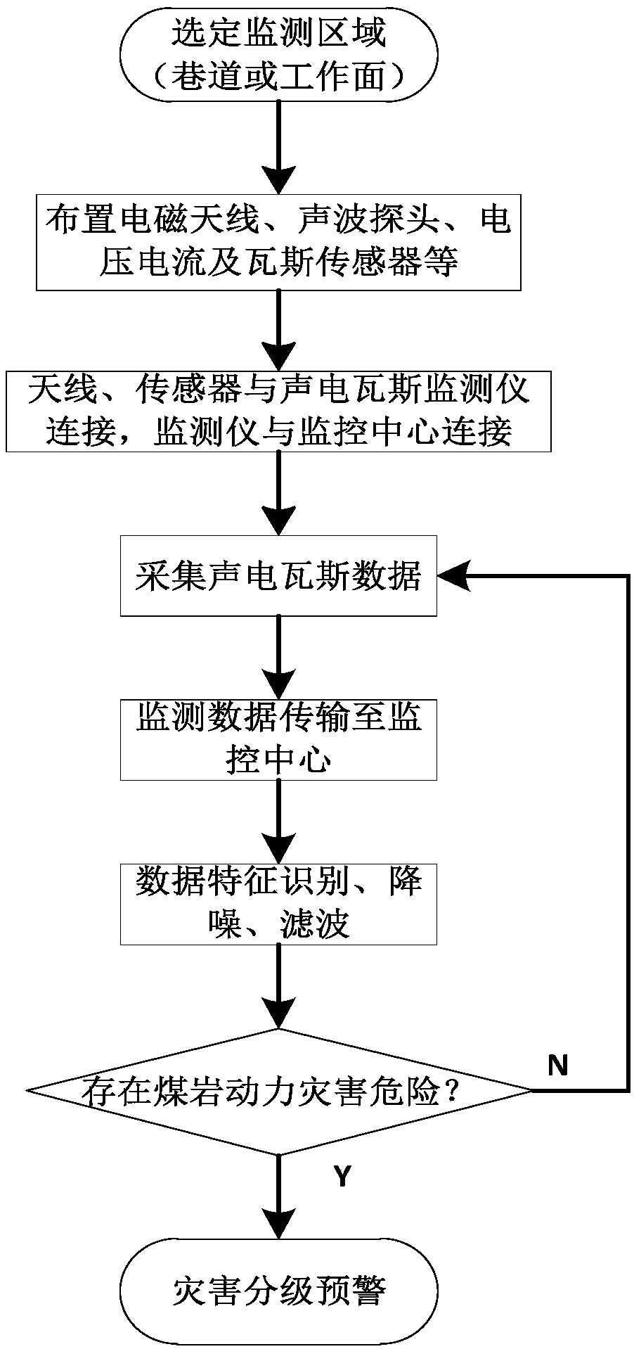
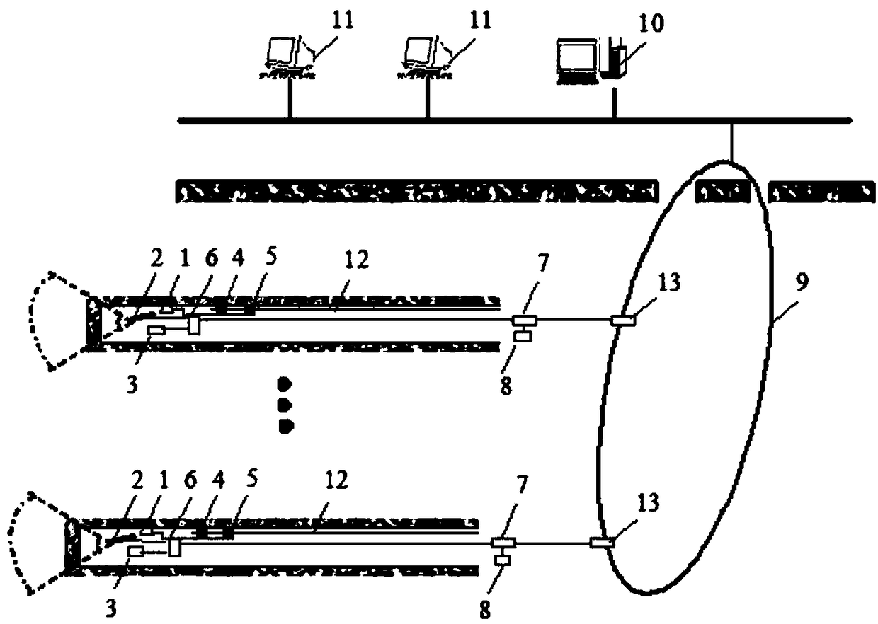
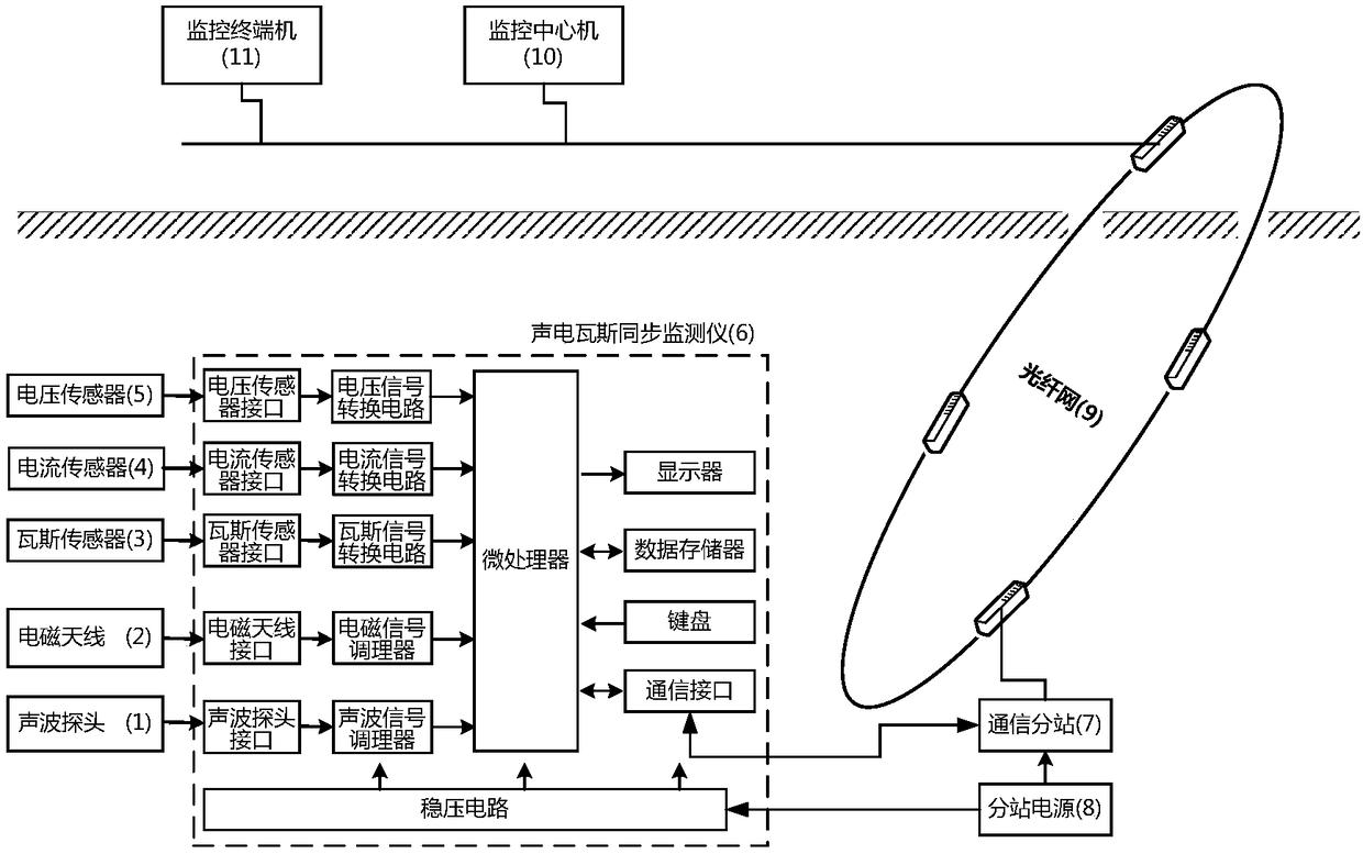
[0022] Real-time automatic monitoring system of sound, electricity and gas for coal and rock dynamic disasters, including sound wave probe, electromagnetic antenna, gas sensor, current sensor, voltage sensor, sound, electricity and gas synchronous monitor, communication substation, substation power supply, optical fiber network, monitoring center computer, Monitoring terminal machine; acoustic wave probe 1, electromagnetic antenna 2, current sensor 4, voltage sensor 5 and gas sensor 3 are connected to the corresponding sensor input interface of the acoustic-electric gas synchronous monitor 6; the communication interface of the acoustic-electric gas synchronous monitor 6 is connected to the communication The input end of the substation 7 is connected, and the communication substation 7 is connected with the monitoring central machine 10 and the monitoring termin...


PUM


Abstract

A real-time automatic monitoring system and method for coal-rock power disaster acoustic-electricity gas, belonging to the field of mine safety and monitoring and control. The system is composed of an acoustic wave probe (1), an electromagnetic antenna (2), a gas sensor (3), a current sensor (4), a voltage sensor (5), an acoustic-electricity gas synchronization monitor (6), a communication substation (7), a substation power source (8), a monitoring centre machine (10), etc. The system receives acoustic waves, electromagnetic radiation and gas signals by means of the acoustic-electricity gas synchronization monitor (6), and can access the voltage sensor (5) to monitor the energization of a power cable and access the current sensor (4) to monitor the working of an electromechanical device. The system identifies the movement of the probe (1) and the antenna (2) and the mining activity through sudden changes of the acoustic waves, electromagnetic and gas signals and the characteristics of acoustic-electricity spectrum in combination with the changes of current and voltage signals. The system pre-warns an abnormal area in front of a working face and the danger of a coal-rock power disaster through effective acoustic waves and electromagnetic signal changes and spectrum characteristics in combination with gas signal change characteristics. The present invention can be applied to the monitoring of an abnormal area in front of a working face and the monitoring and pre-warning of coal and gas outbursts and rock bursts.

Description

technical field [0001] The invention relates to the field of mine safety and monitoring, in particular to a system and method for real-time automatic monitoring of sound, electricity and gas for coal-rock dynamic disasters. Background technique [0002] Coal-rock dynamic disasters in coal mines mainly include coal (rock) and gas (methane or carbon dioxide) outburst, coal and gas extrusion, rock burst, etc. With the increase of mining depth and mining intensity, coal-rock dynamic disasters such as mine gas outburst and rock burst have become increasingly serious and complex, and the risk of disasters has increased significantly. At the same time, some mines that had no dynamic disasters or obvious signs are now also Gradually, it seriously threatens the life safety of underground workers and the normal production of mines. [0003] At present, the prediction of coal-rock dynamic disasters in my country can be roughly divided into two categories: static method and dynamic met...

Claims


Application Information

Patent Timeline
Patent Type & Authority Patents(China)
IPC IPC(8): E21F17/18
CPCE21F17/18
Inventor 王恩元李忠辉陈世海何学秋欧建春
Owner CHINA UNIV OF MINING & TECH
Learn More