Method of using loading force to measure rod pumped well annular space working fluid level and work condition diagnosis method

A technology for pumping well and dynamic liquid level, which is applied in the measurement of the liquid level position of the pumping well in the oil field and the field of oil production in the oil field. Problems such as the position of the force zero point of the power map, to achieve the effects of reliable and timely energy saving, efficiency improvement, accuracy improvement, and less test parameters

Active Publication Date: 2015-04-01
哈尔滨斯特凯峰电子有限公司
View PDF7 Cites 5 Cited by
  • Summary
  • Abstract
  • Description
  • Claims
  • Application Information

AI Technical Summary

Problems solved by technology

[0002] For many years, pumping wells in oil fields have been used to measure the dynamic liquid level in the annular space. Acoustic liquid level testers are generally used to measure the dynamic liquid level. Suspended hard cover (dead oil surface), influence of foam section, or inclined well and other factors, it is difficult to accurately measure the dynamic liquid level in the annulus of the pumping well, or the dynamic liquid level cannot be measured; most of the working conditions of the pumping well are diagnosed during operation The load and displacement ground dynamometer is used to realize the type of working condition by using the measured data playback curve graph. At present, the deformation of the sucker rod is calculated after the force is applied, and it is difficult to determine the position of the zero point of the force on the dynamometer.
It is difficult to realize on-site continuous automatic quantitative measurement by traditional methods; the dynamic liquid level measurement and working condition diagnosis of the pumping well annulus require the use of various instruments, man-machine cooperation, and the auxiliary computer playback graphics comparison can be completed

Method used


Image

  • Method of using loading force to measure rod pumped well annular space working fluid level and work condition diagnosis method
  • Method of using loading force to measure rod pumped well annular space working fluid level and work condition diagnosis method
  • Method of using loading force to measure rod pumped well annular space working fluid level and work condition diagnosis method

Examples


specific Embodiment approach 1

[0046] Specific embodiments one, this embodiment is described a kind of process of measuring the method for pumping well annulus fluid level with load force is:

[0047] During the normal working process of the pumping unit, the wellhead suspension point load force of the pumping well is collected in real time at high speed, and the data collection speed is greater than or equal to 20 times per second, and the time when the crank of the pumping unit reaches the top dead center of the corresponding pumping unit and the time when it is lowered are determined. dead moment

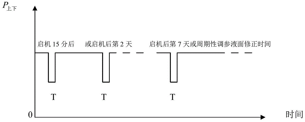
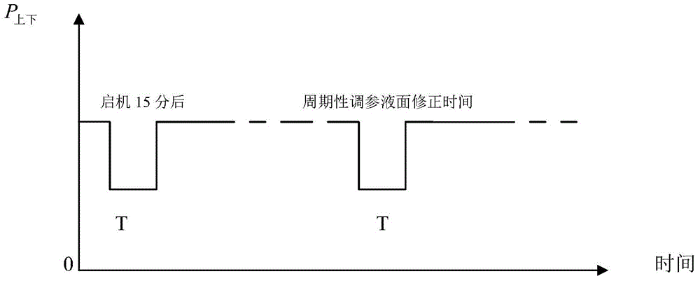
[0048] Step 1. When the working condition parameters need to be measured, the coefficient correction is performed first:

[0049] Adjust the parameters of the pumping well, specifically to control the stroke frequency of the pumping well from the normal operation N to the N after the parameter adjustment 1 , N 1 ≠N and continue to run for a time T, and then return to the stroke times N of normal operation ag...

specific Embodiment approach 2

[0069] Specific embodiment 2. This embodiment is a further limitation of the method for measuring the dynamic liquid level in the annulus of the pumping well with the load force described in the first specific embodiment. In this embodiment, the dynamic liquid level HY of the annular space is obtained. The method is based on the formula:

[0070] HY=(P 上下 -K) / F p

[0071] Obtain the dynamic liquid level HY of the annular space, where: F p Indicates the cross-sectional area of ​​the pumping plunger of the pumping well.

[0072] In the prior art, the method of obtaining the dynamic liquid level in the annular space is based on the mathematical model formula HY=P 上下 / F p get. In this embodiment, when measuring the dynamic liquid level in the annular space, the difference f p ×HY×γ 密 g is related to the weight of the dynamic liquid surface in the annular space, through the change of the actual load force P during the parameter adjustment process 上下 To establish this varia...

specific Embodiment approach 3

[0074] Specific Embodiment 3. This embodiment is a further limitation of the method for measuring the annular dynamic fluid level of the pumping well with the load force described in the specific embodiment 2. In this embodiment, it also includes calculating and obtaining the annular dynamic fluid level. In the step of surface acceleration data a, the obtained annulus dynamic liquid level is corrected by using the formula HY=HY / (1+a) according to the velocity data a to obtain the final annulus dynamic liquid level HY.

[0075] In this embodiment, in the process of measuring the annular dynamic liquid level, the step of measuring the annular space dynamic liquid surface acceleration a is added, and the obtained annular space dynamic liquid level HY is corrected by the acceleration a, thereby eliminating the The influence of the acceleration on the measurement result makes the measurement result closer to the actual value.

[0076] The acceleration a can be based on the formula ...


PUM


Abstract

Provided is a method of using loading force to measure rod pumped well annular space working fluid level and a work condition diagnosis method, relating to the technical field of oil extraction in oil field. The provided method solves the problem that the measuring of oil well work condition parameters is achieved by various instruments and the cooperation of manual work. The extracted oil fluid of the oil well is a three phase stream (oil, water, and gas) which is greatly affected by the gas in the test process, and the online measuring of the working fluid level is difficult. The method comprises the steps of: excluding the gas influence, calculating by weight in the test process; detecting and recording the time of the upper dead point and the lower dead point of each stroke during the data collecting process, so as to divide the collected data into upper stroke data and lower stroke data, eliminating uncertain factor errors and fixed errors by differential process; achieving data reliability by data density ensured by the high speed data collection, periodically disassembling the upper and lower stroke loading force data and time of the rod pumped well; superposing the symmetric areas of the upper and lower stroke data of the running oil pump; using the aforementioned method in combination to achieve on-site measurement of rod pumped well annular space working fluid level and the work condition diagnosis.

Description

technical field [0001] The present application relates to the technical field of oil production in oil fields, in particular to the technical field of oil pumping well liquid level measurement technology. Background technique [0002] For many years, pumping wells in oil fields have been used to measure the dynamic liquid level in the annular space. Acoustic liquid level testers are generally used to measure the dynamic liquid level. Suspended hard cover (dead oil surface), influence of foam section, or inclined well and other factors, it is difficult to accurately measure the dynamic liquid level in the annulus of the pumping well, or the dynamic liquid level cannot be measured; most of the working conditions of the pumping well are diagnosed during operation The load and displacement ground dynamometer is used to realize the measurement, and the type of working condition is judged by the playback curve graph of the measured data. At present, the deformation of the sucker r...

Claims


Application Information

Patent Timeline
Patent Type & Authority Applications(China)
IPC IPC(8): E21B47/047E21B47/009
CPCE21B47/008E21B47/047
Inventor 金凯金奇峰王伟
Owner 哈尔滨斯特凯峰电子有限公司
Why Eureka
Try Eureka