
hydraulic buffer

A technology of hydraulic buffer and buffer cylinder, which is applied in the field of hydraulic buffer, can solve the problems of reduced buffer effect and inability to adjust buffer force, and achieves the effect of maximizing performance and adjustable buffer force.

Active Publication Date: 2019-01-08
JIANGSU ELECTRIC POWER RES INST +3
View PDF5 Cites 0 Cited by
  • Summary
  • Abstract
  • Description
  • Claims
  • Application Information

AI Technical Summary

Problems solved by technology

[0005] The structure of the traditional hydraulic buffer is fixed, and each mechanism can only achieve one kind of buffering effect. The buffering force cannot be adjusted according to the working conditions, and the buffering effect may decrease due to oil leakage and other reasons in the mechanism after working for a long time.

Method used


Image

  • hydraulic buffer
  • hydraulic buffer

Examples


Embodiment Construction

[0020] The present invention will be further described below in conjunction with specific examples.

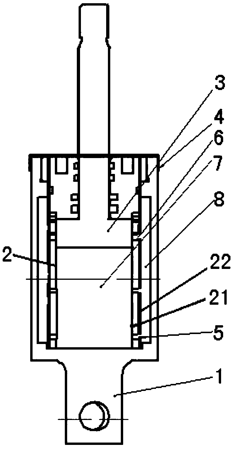
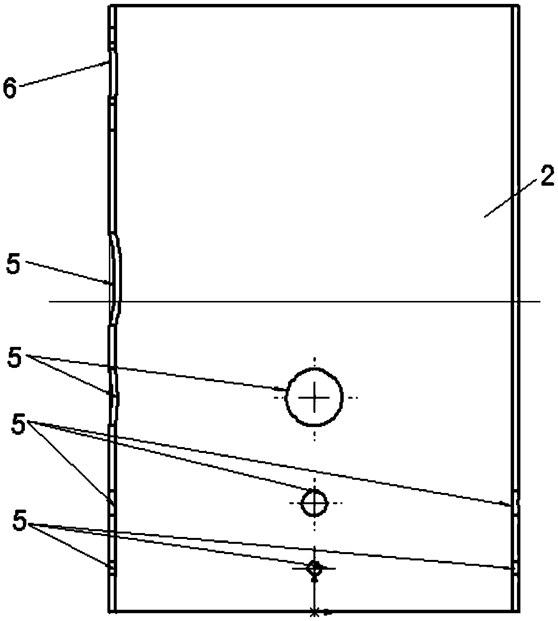
[0021] Such as figure 1 As shown, a hydraulic buffer includes a cylinder base 1, a buffer cylinder 2, a piston 3, and a rotating sleeve 4; the buffer cylinder 2 is fixed in the cylinder base 1, and the buffer cylinder 2 includes a fixed buffer cylinder 21 and a moving buffer cylinder 22 The fixed buffer cylinder 21 is sleeved inside the motion buffer cylinder 22, and the surface corresponding to the fixed buffer cylinder 21 and the motion buffer cylinder 22 is provided with a throttling hole 5 and a return hole 6, and the fixed buffer cylinder 21 is a hollow container. For storing oil, the hollow part formed by the fixed buffer cylinder 21 and the piston 3 is the inner cavity 7; there is a certain gap between the moving buffer cylinder 22 and the cylinder seat 1, and the gap is used as an oil return cavity to form an outer cavity 8; the rotating sleeve 4. Connect with the mot...


PUM


Abstract

The invention discloses a hydraulic buffer. The hydraulic buffer comprises an oil cylinder seat, a buffering cylinder, a piston and a rotary sleeve; the buffering cylinder is installed in the oil cylinder seat and comprises a fixed buffering cylinder body and a movable buffering cylinder body, the fixed buffering cylinder body is installed in the movable buffering cylinder body in a sleeved mode, and throttling holes and reflowing holes are formed in the surfaces of the fixed buffering cylinder body and the movable buffering cylinder body; the fixed buffering cylinder body is used for storing oil liquid, a hollow portion formed between the fixed buffering cylinder body and the piston is an inner cavity, and a certain space is formed between the movable buffering cylinder body and the oil cylinder seat and used as a oil returning cavity to form an outer cavity; and the rotary sleeve and the movable buffering cylinder body are connected to control rotating of the movable buffering cylinder body and adjust the number and size of the aligned throttling holes of the movable buffering cylinder body and the fixed buffering cylinder body, when being subjected to the action of force, the piston moves inwards the buffering cylinder, and the oil liquid is compressed, flows to the outer cavity from the inner cavity through the throttling holes and then flows back to the inner cavity through the reflowing holes to achieve circulation of the oil liquid.

Description

technical field [0001] The invention relates to a hydraulic shock absorber, in particular to a hydraulic shock absorber which adjusts the shock absorbing force according to actual conditions. Background technique [0002] The buffer is a device used to extend the impact load, absorb and transform the energy in the impact load to reduce its adverse consequences, and is widely used in various fields such as lifting transportation, metallurgy, port machinery, and railway vehicles. The performance directly affects many factors such as the service life of the machine and the safety of the operator. Therefore, it plays a very important role in production. [0003] From the perspective of its core buffer components and buffer mechanism, buffers are mainly divided into five categories: mechanical spring buffers, rubber buffers, cylinder buffers, hydraulic buffers, and hydraulic-spring buffers. Among them, the hydraulic buffer can absorb most of the impact energy through the orific...

Claims


Application Information

Patent Timeline
Patent Type & Authority Patents(China)
IPC IPC(8): F16F9/346
CPCF16F9/346
Inventor 杨景刚赵科李洪涛高山贾勇勇陶加贵王静君刘通腾云刘媛李玉杰宋思齐
Owner JIANGSU ELECTRIC POWER RES INST
Learn More