Linear electromagnetic damper and control method thereof
An electromagnetic damper, linear technology, applied in the direction of magnetic spring, spring/shock absorber, spring, etc., can solve the problems of complex structure, fragile, mechanical wear, etc., to achieve strong environmental adaptability, not easy to damage, use Long life effect
- Summary
- Abstract
- Description
- Claims
- Application Information
AI Technical Summary
Problems solved by technology
Method used
Image
Examples
Embodiment 1
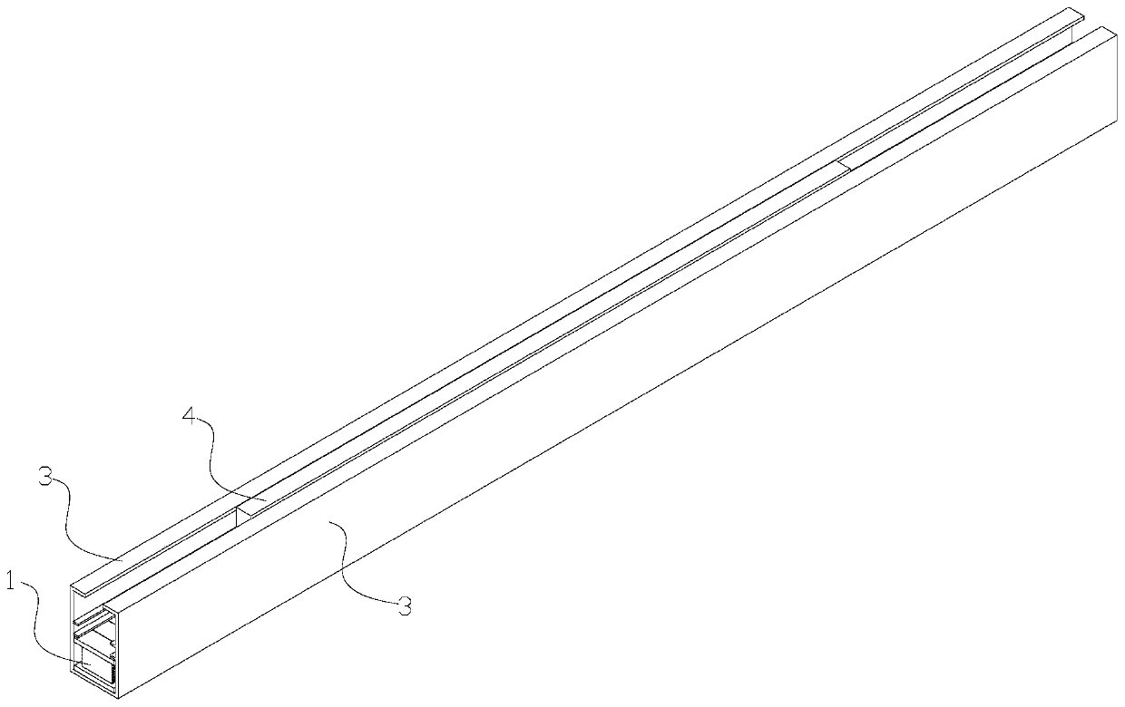
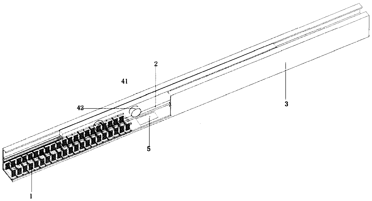
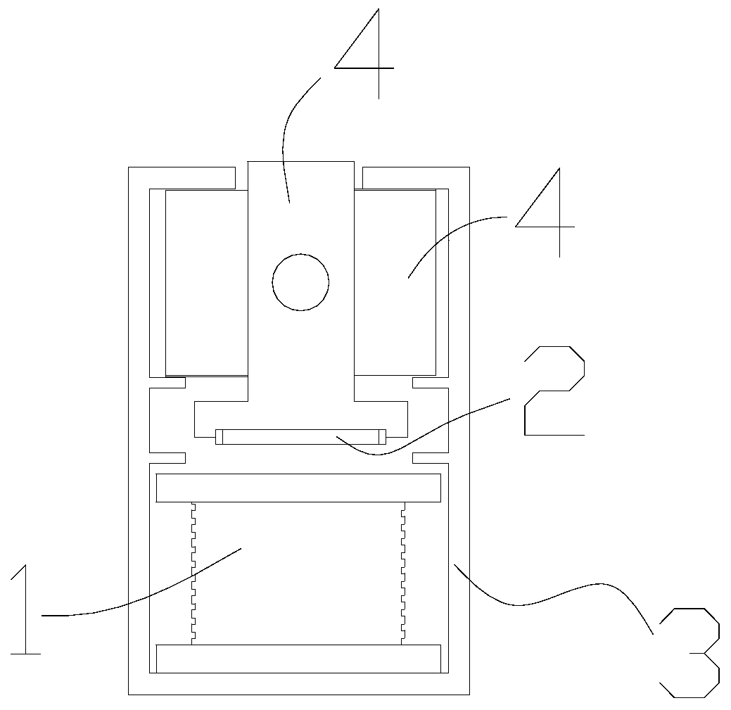
[0042] Such as Figure 1-5 As shown, a linear electromagnetic damper includes a linear induction coil unit 1, a linear magnet unit 2, a guide rail 3, a moving assembly 4 and a buffer control unit 5;
[0043] The linear induction coil unit 1 is arranged in the bottom of the guide rail 3; the moving assembly 4 is arranged on the guide rail 3 and moves with the guide rail 3; the linear magnet unit 2 is arranged on the guide rail 3 Under the bottom of the moving assembly 4; the buffer control unit 5 is connected to the linear induction coil unit 1; when the linear induction coil unit 1 and the linear magnet unit 2 are relatively displaced and electromagnetic cutting magnetic force lines occur, the The linear induction coil unit 1 outputs an induction signal to the buffer control unit 5;
[0044] The linear magnet unit 2 is used to make the linear induction coil unit 1 cut the magnetic field lines generated by the linear magnet unit 2 during the movement process;
[0045] The gui...
Embodiment 2
[0049] Embodiment 2 is the further optimization of embodiment 1;
[0050] Such as Figure 1-5 As shown, the linear induction coil unit 1 is a linear induction coil unit, a curved induction coil unit or an arc induction coil unit; the linear magnet unit 2 is a linear magnet unit, a curved type magnet unit or arc line type magnet unit.
Embodiment 3
[0052] Embodiment 3 is the further optimization of embodiment 1;
[0053] Such as Figure 1-5 As shown, the linear induction coil unit 1 includes N coil combinations 11; each coil combination 11 is arranged linearly in the bottom of the guide rail 3 from left to right; the coil combination 11 includes A first-phase induction coil 111, a second-phase induction coil 112, and a third-phase induction coil 113 arranged linearly in sequence; one line end of the first-phase induction coil 111 of each coil combination 11 is sequentially connected in series; each coil combination 11 One wire end of the second phase induction coil 112 of each coil combination 11 is sequentially connected in series; one wire end of the third phase induction coil 113 of each coil combination 11 is connected in series successively; The other wire end of the first-phase induction coil 111 , the other wire end of the second-phase induction coil 112 and the other wire end of the third-phase induction coil 11...
PUM
 Abstract
Description
Claims
Application Information
 - R&D
- Intellectual Property
- Life Sciences
- Materials
- Tech Scout
- Unparalleled Data Quality
- Higher Quality Content
- 60% Fewer Hallucinations
Browse by: Latest US Patents, China's latest patents, Technical Efficacy Thesaurus, Application Domain, Technology Topic, Popular Technical Reports.
© 2025 PatSnap. All rights reserved.Legal|Privacy policy|Modern Slavery Act Transparency Statement|Sitemap|About US| Contact US: help@patsnap.com


