A steel-plastic composite pipe joint and method thereof

A steel-plastic composite pipe and composite pipe head technology, applied in the direction of pipes/pipe joints/pipe fittings, flange connections, passing elements, etc., can solve the problems of pipes and joints falling off, water leakage, air leakage, etc., and achieve the effect of preventing falling off

Active Publication Date: 2018-10-26
CHINA MCC5 GROUP CORP
View PDF8 Cites 0 Cited by
  • Summary
  • Abstract
  • Description
  • Claims
  • Application Information

AI Technical Summary

Problems solved by technology

[0003] The purpose of the present invention is to overcome the deficiencies of the prior art, provide a steel-plastic composite pipe joint and its method, and solve the problem that relatively thick steel-plastic composite pipe joints are not firmly connected, and the pipes and joints are prone to fall off, or leak or leak. gas problem

Method used


Image

  • A steel-plastic composite pipe joint and method thereof
  • A steel-plastic composite pipe joint and method thereof
  • A steel-plastic composite pipe joint and method thereof

Examples


Embodiment

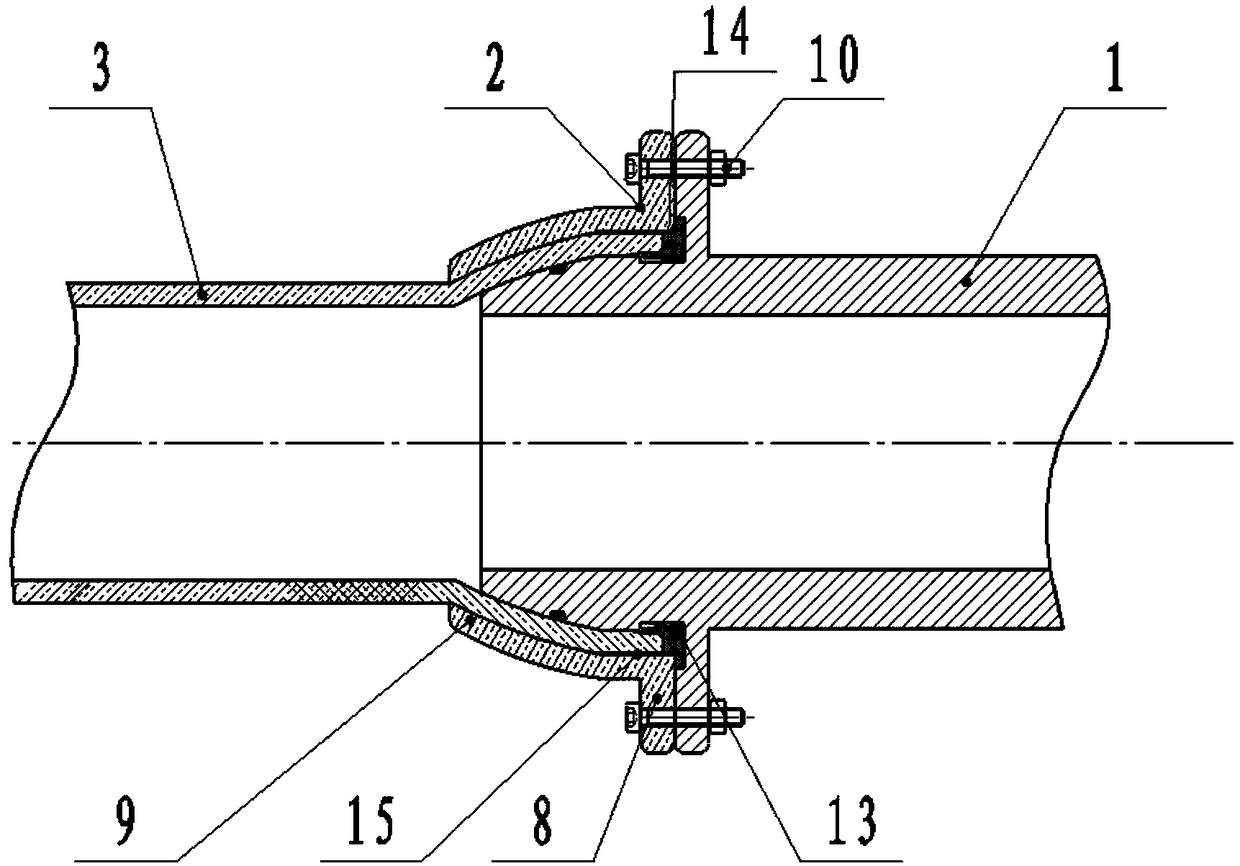
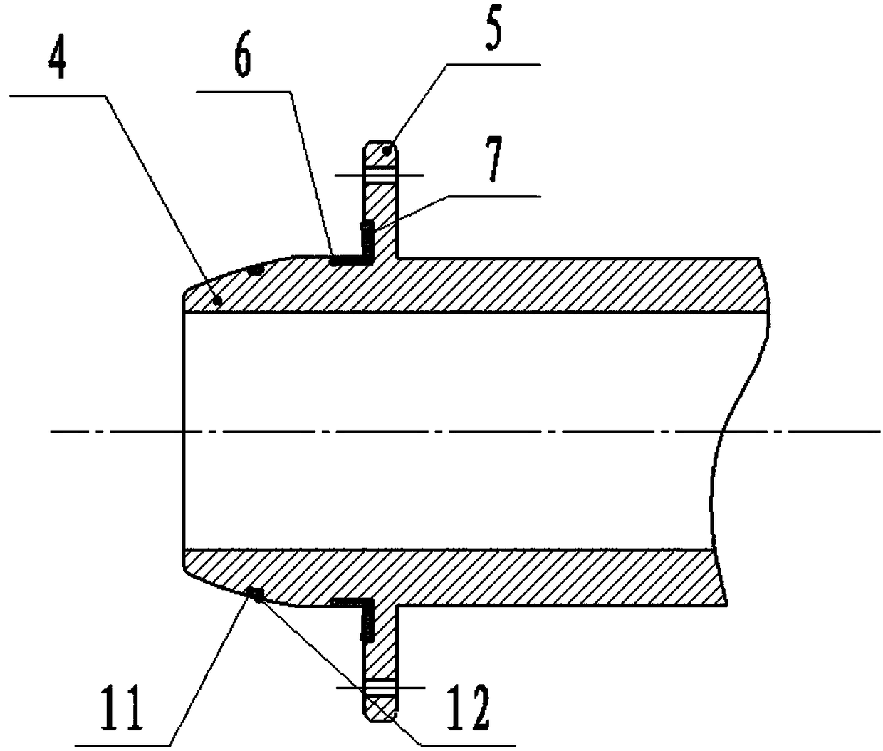
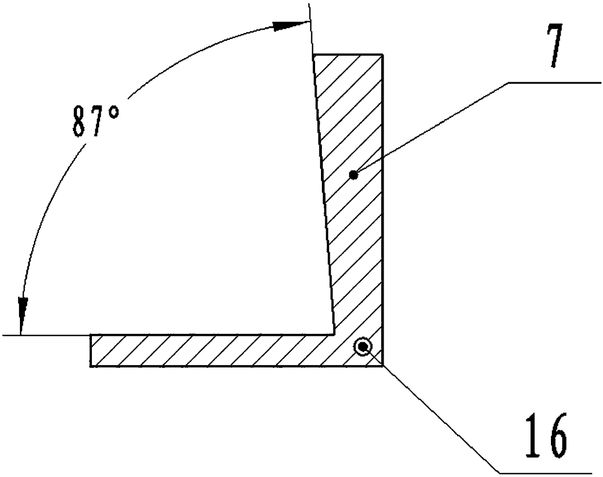
[0030] Such as Figure 1-3 As shown, a steel-plastic composite pipe joint of the present invention includes a connector body 1 and a connection compression set 2, both of which are made of forged cast iron and then clamped by machine, such as figure 1 shown, with figure 1 Only the connection structure of one end of the connector body 1 is shown. Since the connectors at both ends are the same, both ends of the connector body 1 are provided with a tapered joint 4 for inserting the steel-plastic composite pipe head 3, and the connector body inside the tapered joint 4 1 is provided with a first connecting flange 5, and a plurality of L-shaped grooves 6 are arranged around the angled surface between the outer surface of the first connecting flange 5 and the main body 1 of the connecting head, and an L-shaped tension block 7 is arranged in the L-shaped groove 6 The connection compression set 2 includes a second connection flange 8 and a compression sleeve 9, the compression sleeve ...

Embodiment 2

[0038] Such as Figure 1-3 As shown, a steel-plastic composite pipe connection method of the present invention comprises steps:

[0039] Step 1) Set the connection compression kit 2 on the steel-plastic composite pipe;

[0040] Step 2) The expansion of the steel-plastic composite pipe head 3 is matched with the tapered joint 4;

[0041] Step 3) Put a sealing ring 12 in the annular groove 11 on the tapered joint 4; put a sealing ring 14 at the angle between the outer surface of the first connecting flange 5 and the main body 1 of the connecting head;

[0042] Step 4) Put the flared steel-plastic composite pipe head 3 on the tapered joint 4 until the end surface of the steel-plastic composite pipe head 3 is squeezed on the sealing ring 14;

[0043] Step 5) Move the connection compression set 2 closer to the main body 1 of the connection head. After the connection compression set 2 is close to the flare of the steel-plastic composite pipe head 3, rotate the connection compressi...


PUM


Abstract

The invention discloses a steel-plastic composite pipe connector and a method thereof. The steel-plastic composite pipe connector comprises a connecting head body and a connecting pressing set. The two ends of the connecting head body are provided with conical connectors, wherein a steel-plastic composite pipe head can be sleeved with the conical connectors in an inserted manner. First connecting flanges are arranged at the positions, on the inner sides of the conical connectors, on the connecting head body. Multiple L-shaped grooves are formed in the included angle faces of the outer side faces of the first connecting flanges and the connecting head body in a surrounding manner. L-shaped tensioning blocks are arranged in the L-shaped grooves. The connecting pressing set comprises second connecting flanges and pressing sleeves. The pressing sleeves are also in a cone shape, and the second connecting flanges are arranged at the large-head ends of the pressing sleeves. The connecting pressing set can be used for clamping and sealing the steel-plastic composite pipe head by being arranged on the conical connectors in a sleeving manner, and the second connecting flanges and the first connecting flanges are matched and are firmly connected through bolts. The problems that a relatively thick steel-plastic composite pipe connector is not firm in connection, and a pipeline and the connector are likely to be disengaged or water leakage and gas leakage are likely to happen are solved.

Description

technical field [0001] The invention relates to the field of connecting joints of pipe fittings, in particular to a steel-plastic composite pipe joint and a method thereof. Background technique [0002] Steel-plastic composite pipes are often used in gas or water pipelines. The connection joints of relatively thin steel-plastic composite pipes (with a diameter less than 5cm) all use ferrule-type copper pipe joints or compression-type copper pipe joints, which also appear in the prior art. A connector with a clamping ring can be used to clamp the pipe and the connector conveniently. When connecting a thicker steel-plastic composite pipe (diameter greater than 5cm), it is more difficult to use the above-mentioned connector to connect, which will lead to poor connection. It is firm, and it is easy for pipes and joints to fall off, or to leak water or air. Contents of the invention [0003] The purpose of the present invention is to overcome the deficiencies of the prior art,...

Claims


Application Information

Patent Timeline
Patent Type & Authority Patents(China)
IPC IPC(8): F16L23/024F16L23/028F16L23/18
CPCF16L23/024F16L23/028F16L23/18
Inventor 张应成赵中华石磊
Owner CHINA MCC5 GROUP CORP
Why Eureka
Try Eureka