
A high voltage current monitoring circuit

A technology for monitoring circuits and high-voltage currents, applied in the direction of measuring current/voltage, measuring only current, measuring electrical variables, etc., can solve problems such as affecting sampling accuracy, affecting output accuracy, and ordinary production lines cannot produce circuits, achieving easy integration, high The effect of input voltage range and sampling amplification accuracy, broad application prospects and economic benefits

Active Publication Date: 2019-04-02
XIAN MICROELECTRONICS TECH INST
View PDF6 Cites 0 Cited by
  • Summary
  • Abstract
  • Description
  • Claims
  • Application Information

AI Technical Summary

Problems solved by technology

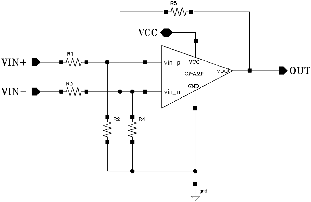
[0003] Commonly used high-voltage current monitoring circuits have two configurations. The first type uses a differential amplifier configuration, such as the INA117 circuit of a foreign TI company. The structure of its application is as follows: image 3 As shown, this configuration internally uses operational amplifiers and resistors to build a subtractor circuit to achieve differential mode signal acquisition and output in high common mode signals, but the main disadvantages of this configuration are ① input common mode voltage range It is determined by the resistance ratio of R1 and R2, so the higher input common mode range of the circuit requires a large ratio of R1 / R2
This results in a lower input voltage to the op amp when the input common-mode voltage is lower
②The input terminal has a certain current to the ground, especially the current flowing into the VIN- terminal will cause a voltage drop on the sampling resistor, which affects the sampling accuracy, and the current increases linearly with the increase of the common-mode voltage (bus voltage)
Therefore, the resistance value of (R1+R2) must be large enough during design, which will take up a lot of layout area
And a larger resistance will cause the input offset current of the op amp to generate a larger error voltage on it
③The ability of the circuit to suppress the common-mode voltage depends heavily on the resistance accuracy. Ideally, the common-mode gain is zero. In fact, the greater the relative resistance error, the circuit common-mode gain will also increase linearly, which will directly affect the output accuracy.
However, no matter which design configuration is adopted, in order to meet the requirement that the input voltage can cover the power supply voltage, it puts forward higher requirements for the monolithic integrated circuit process, that is, the withstand voltage of the device must be greater than the system power supply voltage, and the DC / DC Module as an example, the general bus voltage range includes 47V, 100V, 200V, etc., the process conditions require at least the working withstand voltage of the device to be higher than 47V, 100V, 200V, which requires high technical conditions for the process line, and also limits the common The production line cannot produce such circuits

Method used


Image

  • A high voltage current monitoring circuit
  • A high voltage current monitoring circuit
  • A high voltage current monitoring circuit

Examples


Embodiment Construction

[0030] The present invention will be further described in detail below in conjunction with specific embodiments, which are explanations of the present invention rather than limitations.

[0031] A high-voltage current monitoring circuit of the present invention, such as Figure 4 As shown, two-stage operational amplifiers are used to realize the functions of high-voltage sampling-current-voltage conversion and amplification respectively.

[0032] In the present invention, the sampling voltage (V IN+ —V IN- ) into the current signal I, according to the virtual short-virtual break method of the operational amplifier, it can be calculated

[0033] (V IN+ -V IN- )=R1×I (1)

[0034] The current signal I is transmitted from the high voltage side to the low voltage side through the three-stage Darlington transistors Q1Q2, Q3Q4, and Q5Q6, and is converted into a voltage signal by the resistor R3, and then amplified and output by the second operational amplifier amp2. Wherein, th...


PUM


Abstract

The invention relates to a high voltage flow monitoring circuit. The high voltage flow monitoring circuit comprises a first operation amplifier and a second operation amplifier, wherein the first operation amplifier is connected with a bus voltage and a positive power source supply, the first operation amplifier comprises a voltage division circuit connected between the bus voltage and a negative power source, a non-inverting phase input end and an inverting phase input end of the first operation amplifier are respectively connected with two ends of a high side sampling resistor through a resistor R1 and a resistor R2, an output end of the first operation amplifier is connected with a base electrode of an output Darlington tube, a voltage division output end of the first operation amplifier is connected with a base electrode of a corresponding voltage division Darlington tube, the voltage division Darlington tube is sequentially cascaded between the non-inverting phase input end of the first operation amplifier and a collector electrode of the output Darlington tube, an emitter electrode of the output Darlington tube is in ground connection through a resistor R3, the second operation amplifier is connected with the voltage division output end of the first operation amplifier and the positive power source supply, a non-inverting phase input end of the second operation amplifier is connected with an emitter electrode of the output Darlington tube, an inverting phase input end of the second operation amplifier is in ground connection through a resistor R4 and is connected with an output end of the second operation amplifier through a resistor R5, and a monitoring signal is outputted by the output end.

Description

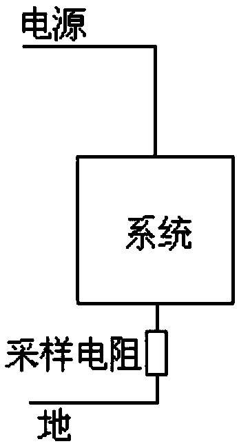
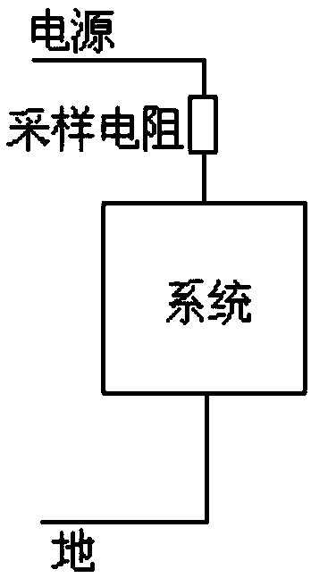
technical field [0001] The invention relates to the field of semiconductor integrated circuits, in particular to a high-voltage current monitoring circuit. Background technique [0002] The current monitoring circuit, as the name suggests, is a circuit that samples the system current signal and amplifies the output. The general method of sampling current is to convert the current signal of the system into a voltage signal through an external sampling resistor. According to whether the sampling resistor is connected to the power supply or ground and is referred to as a high-side sampling mode such as figure 2 shown, or low-side sampling mode as figure 1 As shown; the advantage of low-side sampling is that the sampling voltage signal is referenced to the ground potential, and subsequent signal processing can be directly performed, but its disadvantages are also obvious, that is, the actual reference 'ground' potential of the system is raised due to the existence of the sampl...

Claims


Application Information

Patent Timeline
Patent Type & Authority Patents(China)
IPC IPC(8): G01R19/00
CPCG01R19/0092
Inventor 赵明王勇
Owner XIAN MICROELECTRONICS TECH INST
Learn More