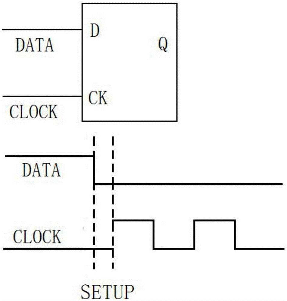
D flip-flop setup time measuring circuit and D flip-flop setup time measuring method
A technology for establishing time and measuring circuits, applied in the direction of measuring electrical variables, measuring electricity, measuring devices, etc., can solve the problem of inaccurate establishment time of D flip-flops
- Summary
- Abstract
- Description
- Claims
- Application Information
AI Technical Summary
Problems solved by technology
Method used
Image

Examples
Embodiment 1
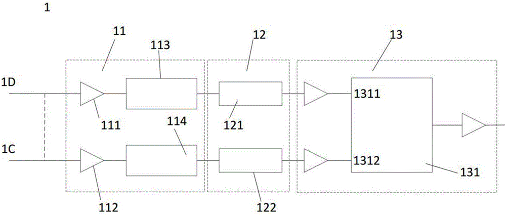
[0064] The present invention provides a D flip-flop settling time measuring circuit 1, which is used to measure the settling time of the D flip-flop when the output signal flips from low to high. The schematic diagram is as follows image 3 shown. The D flip-flop setup time measurement circuit 1 includes: a first input unit 11 , a first conversion unit 12 and a first output unit 13 .
[0065] Specifically, the first input unit 11 includes two buffers and two delay chains, the two buffers are respectively the first data buffer 111 and the first clock buffer 112, and the two delay chains are The chains are respectively the first data delay chain 113 and the first clock delay chain 114, one end of the first data delay chain 113 is connected with the first data buffer 111, and the first clock delay chain 114 One end of is connected to the first clock buffer 112; specifically, the first data delay chain 113 and the first clock delay chain 114 are delay chains formed by p buffers c...
Embodiment 2
[0071] The present invention provides another measurement circuit 2 of D flip-flop settling time, which is used to measure the settling time of D flip-flop when the output signal is flipped from high to low. The schematic diagram is as follows Figure 4 shown. The D flip-flop setup time measurement circuit 2 includes: a second input unit 21 , a second conversion unit 22 and a second output unit 23 .
[0072] Specifically, the first input unit 11 includes an inverter 211, a second clock buffer 212, and two delay chains, and the two delay chains are respectively the second data delay chain 213 and the second clock delay chain 213. Time chain 214, one end of the second data delay chain 213 is connected to the inverter 211, and one end of the second clock delay chain 214 is connected to the second clock buffer 212; specifically, the Both the second data delay chain 213 and the second clock delay chain 214 are delay chains formed by q buffers connected in series, and q is a non-ze...
Embodiment 3
[0078] A method for measuring the establishment time of a D flip-flop, which is used to measure the establishment time of the D flip-flop when the output signal flips from low to high. The specific flow diagram is as follows Figure 5 shown. The measuring method of described D flip-flop setup time comprises the steps:
[0079] Step S51: when n buffers are added to the first clock delay chain, the output signal of the measurement circuit of the D flip-flop setup time is reversed for the first time;
[0080] Step S52: Adjust the voltage value of the first voltage source to reach the critical state V critical , the output signal of the D flip-flop settling time measurement circuit is not inverted, at V critical When +ΔV, the output signal flips for the first time, and the setup time T of the first D flip-flop is obtained setup1 ,at this time Wherein, ΔV is the adjustable minimum step size of the first voltage source, for the critical state V critical The average delay of ...
PUM
 Abstract
Description
Claims
Application Information
 - R&D
- Intellectual Property
- Life Sciences
- Materials
- Tech Scout
- Unparalleled Data Quality
- Higher Quality Content
- 60% Fewer Hallucinations
Browse by: Latest US Patents, China's latest patents, Technical Efficacy Thesaurus, Application Domain, Technology Topic, Popular Technical Reports.
© 2025 PatSnap. All rights reserved.Legal|Privacy policy|Modern Slavery Act Transparency Statement|Sitemap|About US| Contact US: help@patsnap.com