Optical fiber winding device

A fiber winding and optical fiber technology, applied in the field of optical fiber operation, can solve the problems of easy loosening of optical fibers, low efficiency, inconvenient operation, etc., and achieve the effects of good storage effect, convenient operation and high fiber winding efficiency.

Pending Publication Date: 2017-05-31
谢建毫
View PDF11 Cites 0 Cited by
  • Summary
  • Abstract
  • Description
  • Claims
  • Application Information

AI Technical Summary

Problems solved by technology

The above-mentioned fiber winding method has problems such as low efficiency, inconvenient operation, and easy loosening of the optical fiber.

Method used


Image

  • Optical fiber winding device
  • Optical fiber winding device
  • Optical fiber winding device

Examples


Embodiment Construction

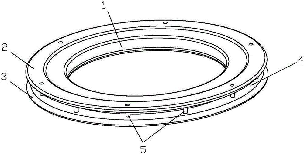
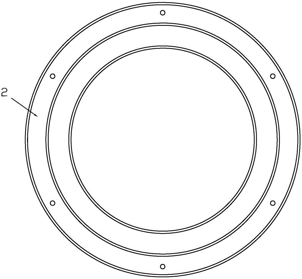
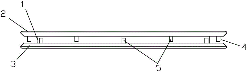
[0019] see Figure 1-Figure 3 . An optical fiber winding device, comprising a fiber winding shaft 1, a first cover plate 2 and a second cover plate 3, the first cover plate 2 and the second cover plate 3 are respectively arranged at both ends of the fiber winding shaft 1, the The first cover plate 2 and the second cover plate 3 are parallel to each other, the fiber shaft 1, the first cover plate 2 and the second cover plate 3 are concentric circles, the first cover plate 2 and the second cover plate A winding fiber groove 4 is formed between the two cover plates 3, and the winding fiber shaft 1, the first cover plate 2 and the second cover plate 3 are connected in an I-shape. The first cover plate 2 and the second cover plate 3 are evenly spaced with a number of soft elastic fiber retaining posts 5, the fiber retaining posts 5 on the first cover plate 2 and the fiber retaining posts on the second cover plate 3 5 are distributed across, and the fiber retaining post 5 is arran...


PUM


Abstract

The invention discloses an optical fiber winding device which comprises a fiber winding shaft, a first cover plate and a second cover plate, wherein the fiber winding shaft, the first cover plate and the second cover plate are concentrically circular; a fiber winding slot is formed between the first cover plate and the second cover plate; a plurality of soft elastic fiber stop columns are uniformly arranged on the first cover plate and the second cover plate in a spacing manner; the fiber stop columns are arranged at an inlet of the fiber winding slot. During use, one end of an optical fiber is fixed firstly, and the optical fiber is wound into the fiber winding slot through a hand; the soft elastic fiber stop columns can be deformed under pressure, so that the optical fiber can be successfully wound at the bottom of the fiber winding slot; after the optical fiber is wound into the fiber winding slot, the fiber stop columns are not pressed and can be returned to the original shape to stop the optical fiber in the fiber winding slot from being popped out; the fiber winding efficiency is high, and the collection effect is good; furthermore, when needing to be used, the optical fiber can be released outside one section by one section; the minimum length of the optical fiber released at each time is equal to a radian distance between every two fiber stop columns; the optical fiber with a specific length is released according to a requirement, and the optical fiber which is not released is still stopped in the fiber winding slot; therefore, the optical fiber winding device is more convenient to operate.

Description

technical field [0001] The invention relates to the field of optical fiber operation, in particular to an optical fiber winding device. Background technique [0002] Optical fiber uses the principle of total reflection of light as a tool for light transmission. Its structure includes a concentric core and cladding. The main component of the core is silicon dioxide and a small amount of dopants such as phosphorus pentoxide and germanium dioxide. , while the main component of the cladding is high-purity silicon dioxide and a small amount of doped fluorine or boron, and the light is enclosed and transmitted in the core. Optical fibers are very fragile and easy to break. If the cladding is damaged, the strength of the optical fiber will be greatly reduced, and light leakage may occur at the same time. Chemicals, heat, crushing, and scratching can all cause damage to optical fibers. [0003] In the process of operating the optical fiber, the optical fiber needs to be wound, and...

Claims


Application Information

Patent Timeline
Patent Type & Authority Applications(China)
IPC IPC(8): G02B6/44
CPCG02B6/4457
Inventor 谢建毫梁其泳
Owner 谢建毫
Why Eureka
Try Eureka