Hydraulic support electrohydraulic control device

A technology of electro-hydraulic control and hydraulic support, which is applied in pillars/supports, mining equipment, earthwork drilling and mining, etc., and can solve the problems of fixed controller position and inconvenient operation for workers

Active Publication Date: 2019-04-16
CHONGQING VOCATIONAL INST OF ENG
View PDF11 Cites 0 Cited by
  • Summary
  • Abstract
  • Description
  • Claims
  • Application Information

AI Technical Summary

Problems solved by technology

[0004] The present invention intends to provide an electro-hydraulic control device for a hydraulic support to solve t

Method used


Image

  • Hydraulic support electrohydraulic control device
  • Hydraulic support electrohydraulic control device
  • Hydraulic support electrohydraulic control device

Examples


Embodiment Construction

[0021] The following is further described in detail through specific implementation methods:

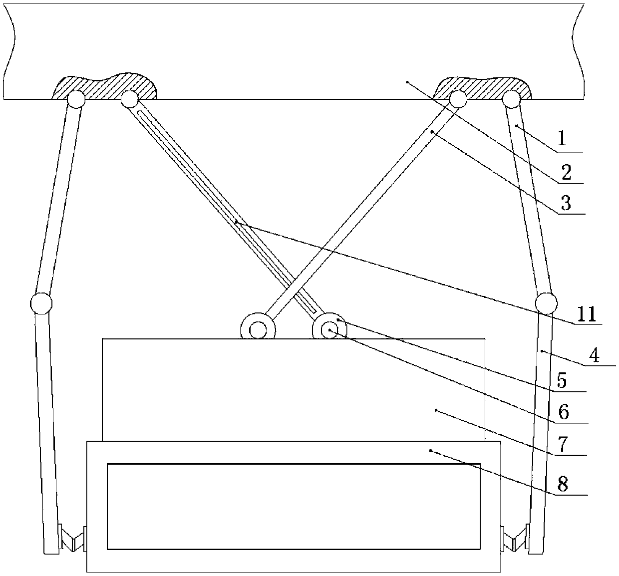
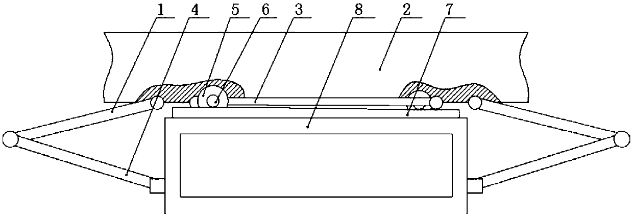
[0022] The reference signs in the drawings of the description include: the second connecting rod 1, the top beam 2, the cleaning rod 3, the first connecting rod 4, the roller 5, the telescopic rod 6, the protective door 7, the installation box 8, the chute 9, the convex 10, guide groove 11.

[0023] Such as figure 1 As shown, an electro-hydraulic control device for a hydraulic support includes an installation box 8 for installing the controller. The front side of the installation box 8 is open, and a vertical sliding protective door 7 is installed at the opening. Adopt glass door, be connected with connecting spring between protective door 7 and installation box 8 bottoms.

[0024] The left and right sides of the installation box 8 are hinged with first connecting rods 4 through hinges, and the upper ends of the two first connecting rods 4 are hinged with second connecting rods 1, ...


PUM


Abstract

The invention relates to the technical field of hydraulic supports, in particular to a Hydraulic support electrohydraulic control device. The hydraulic support electrohydraulic control device comprises a mounting box for mounting of a controller. First connecting rods are hinged to the two sides of the mounting box, second connecting rods are hinged to the free ends of the first connecting rods, and the second connecting rods are hinged to a top beam of a support. The problems that in the prior art, the controller is fixed, and operation of a worker is not convenient are solved.

Description

technical field [0001] The invention relates to the technical field of hydraulic supports, in particular to an electro-hydraulic control device for hydraulic supports. Background technique [0002] Hydraulic support is an important part of fully mechanized mining equipment in coal mines. It uses hydraulic pressure as power to realize movements such as lifting and moving forward. It can reliably and effectively support and control the roof of the working face, isolate the goaf, and prevent gangue from entering the mining face and Advance the conveyor. The labor intensity of coal miners is reduced, and the life safety of coal miners is guaranteed to the greatest extent. [0003] The electro-hydraulic controller is an indispensable part of the work of the hydraulic support. The existing controller is mostly installed at the bottom of the top beam of the hydraulic support, and its position cannot be adjusted. When the goaf is high, the controller As the top beam rises to a hig...

Claims


Application Information

Patent Timeline
IPC IPC(8): E21D15/45E21D15/50
CPCE21D15/45E21D15/50
Inventor 车林仙张彩芳王敬东李雨宣
Owner CHONGQING VOCATIONAL INST OF ENG
Why Eureka
Try Eureka