OLED display with touch function and method of making the same
A technology of touch function and display screen, which is applied in the input/output process of data processing, identification devices, instruments, etc., can solve the problems of large thickness of LCD display screen and unsuitable development trend of ultra-thin touch screen display device, etc. Achieve the effect of thinning and simple overall structure, reducing production cost and simplifying process
- Summary
- Abstract
- Description
- Claims
- Application Information
AI Technical Summary
Problems solved by technology
Method used
Image
Examples
Embodiment 1
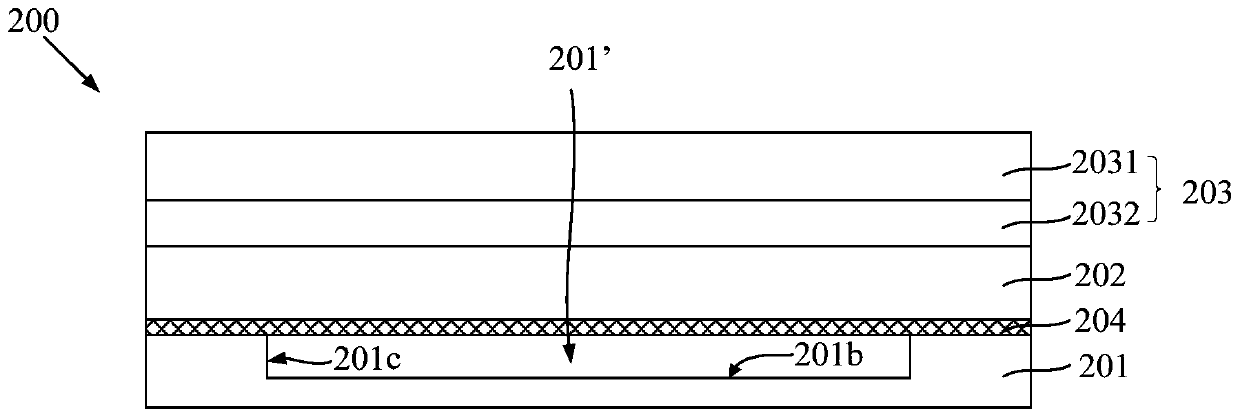
[0029] Such as figure 2 As shown, this embodiment provides an OLED display screen 200 with a touch function, including an OLED cover plate 201, an OLED substrate 202, and a touch screen 203 arranged in sequence, and a 3D film is arranged between the OLED cover plate 201 and the OLED substrate 202 204 , the side of the OLED cover plate 201 facing the OLED substrate 202 has a pit 201 ′, and the 3D film 204 covers the side of the OLED cover plate 201 facing the OLED substrate 202 .
[0030] The OLED substrate 202 is used to emit light and display images, and may include a base and a pixel unit array disposed on the base. The substrate includes a display area (pixel area) and a non-display area (frame area), and the display area is formed with scan lines, data lines intersecting with the scan lines, and a pixel unit array defined by the scan lines and data lines . Various wires are formed in the non-display area, such as power wires and clock wires, and gate drive circuits and ...
Embodiment 2
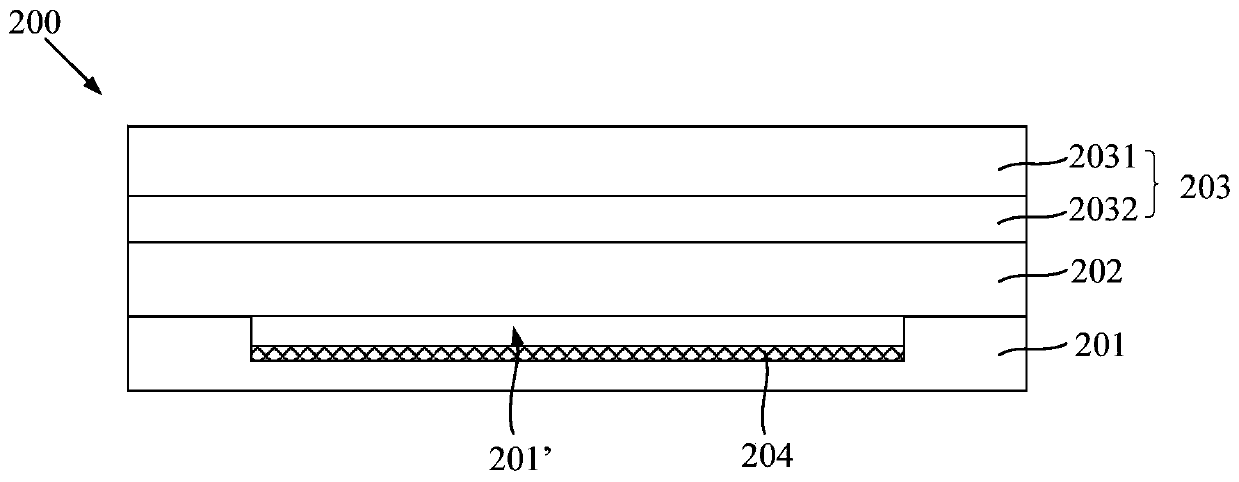
[0041] Such as image 3 As shown, this embodiment provides an OLED display screen with a touch function, including an OLED cover plate 201, an OLED substrate 202, and a touch screen 203 arranged in sequence, and a 3D film 204 is arranged between the OLED cover plate 201 and the OLED substrate 202 , the side of the OLED cover plate 201 facing the OLED substrate 202 has a pit 201 ′. The difference between this embodiment and the first embodiment is that the 3D film 204 is located in the pit 201'. Specifically, the 3D film 204 may be disposed at the bottom of the pit 201', and the 3D film 204 covers the entire area of the bottom of the pit 201'. Because the area of the bottom of the pit 201' is generally larger than the area of the display area, the 3D film 204 covers the entire area of the bottom of the pit 201', which can ensure that the 3D film 204 corresponds to the display area. Because the depth of the pit 201' is usually greater than the thickness of the 3D film ...
Embodiment 3
[0043] Such as Figure 4 As shown, this embodiment provides an OLED display screen with a touch function, including an OLED cover plate 201, an OLED substrate 202, and a touch screen 203 arranged in sequence, and a 3D film 204 is arranged between the OLED cover plate 201 and the OLED substrate 202 , the side of the OLED cover plate 201 facing the OLED substrate 202 has a pit 201 ′. The difference between this embodiment and other embodiments is that a part of the 3D film 204 is located in the recess 201', and a part covers the side of the OLED cover plate 201 facing the OLED substrate 202. Specifically, in Figure 4 Among them, the 3D film 204 covers the entire area of the side of the OLED cover plate 201 facing the OLED substrate 202, that is, the 3D film 204 not only covers the bottom and side walls of the pit 201′, but also covers the area of the side of the OLED cover plate 201 facing the OLED substrate 202. other areas.
PUM
| Property | Measurement | Unit |
|---|---|---|
| depth | aaaaa | aaaaa |
Abstract
Description
Claims
Application Information
 - R&D
- Intellectual Property
- Life Sciences
- Materials
- Tech Scout
- Unparalleled Data Quality
- Higher Quality Content
- 60% Fewer Hallucinations
Browse by: Latest US Patents, China's latest patents, Technical Efficacy Thesaurus, Application Domain, Technology Topic, Popular Technical Reports.
© 2025 PatSnap. All rights reserved.Legal|Privacy policy|Modern Slavery Act Transparency Statement|Sitemap|About US| Contact US: help@patsnap.com


