Drive device and method of display panel

A technology of a driving device and a driving method, which is applied to static indicators, instruments, etc., can solve the problem of uneven lighting and darkness of pixels, and achieve the effect of improving uneven brightness.

Active Publication Date: 2017-05-31
TCL CHINA STAR OPTOELECTRONICS TECH CO LTD
View PDF5 Cites 10 Cited by
  • Summary
  • Abstract
  • Description
  • Claims
  • Application Information

AI Technical Summary

Problems solved by technology

[0004] The technical problem mainly solved by the present invention is to provide a driving device and a driving method of a display panel, which can improve the problem of uneven lighting and darkening of pixels in the display panel.

Method used


Image

  • Drive device and method of display panel
  • Drive device and method of display panel
  • Drive device and method of display panel

Examples


Embodiment Construction

[0023] Certain words are used to refer to specific components in the description and claims, and those skilled in the art should understand that manufacturers may use different terms to refer to the same component. The specification and claims do not use the difference in name as a way to distinguish components, but use the difference in function of components as a basis for distinction. The present invention will be described in detail below in conjunction with the accompanying drawings and embodiments.

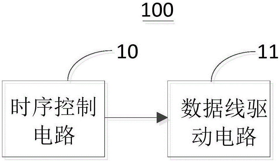
[0024] image 3 It is a structural schematic diagram of the driving device of the display panel according to the first embodiment of the present invention. Such as image 3 As shown, the driving device 100 includes a timing control circuit 10 and a data line driving circuit 11 .

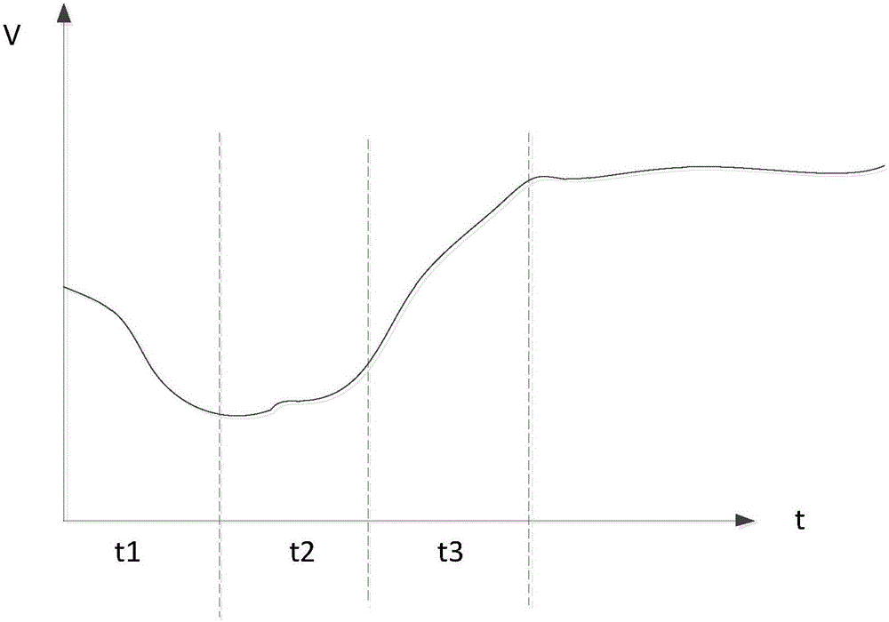
[0025] The timing control circuit 10 is used to receive the current data frame and parse the current data frame to obtain a frame start signal to be output, and generate a precharge signal and a...


PUM


Abstract

The invention discloses a drive device and a drive method of a display panel. The drive device comprises a time sequence control circuit and a data line drive circuit, wherein the time sequence control circuit is used for receiving a current data frame, analyzing the current data frame so that a to-be-output frame opening signal is obtained, and generating a precharge signal and a scanning clock pulse signal according to the frame opening signal, and the precharge signal is output earlier than the scanning clock pulse signal; the data line drive circuit is used for outputting a first charging voltage signal to the data lines under the control of the precharge signal so that after stray capacitors of the data lines are precharged, a second charging voltage signal is output to the data lines, and the pixel points are charged line by line under the control of the scanning clock pulse signal. With the adoption of the above manner, the problem that the luminance of the pixel points in the display panel is nonuniform since the stray capacitors are arranged in the data lines is solved.

Description

technical field [0001] The invention relates to the field of liquid crystal display, in particular to a driving device and a driving method of a display panel. Background technique [0002] In the driving process of the traditional display panel, it is necessary to charge the pixels in the display panel row by row before displaying images. In the actual charging process, since the entire data line has a large parasitic capacitance and stores negative charges, the data line driving circuit installed in the display panel needs to draw a large current to fully charge the parasitic capacitance of the data line first. At this time, if the self-thrusting force of the data line driving circuit is insufficient, the charging voltage will be pulled down, so that the pixels with positive polarity in the first few rows will not be fully charged, and then the brightness of the pixels with positive polarity in these rows will be dim. When the parasitic capacitance on the data line is ful...

Claims


Application Information

Patent Timeline
Patent Type & Authority Applications(China)
IPC IPC(8): G09G3/36
CPCG09G3/36G09G3/3648G09G3/3611G09G2310/08G09G3/3674G09G3/3685G09G3/3696G09G2310/0251G09G2320/0233
Inventor 吴宇王磊
Owner TCL CHINA STAR OPTOELECTRONICS TECH CO LTD
Why Eureka
Try Eureka