
Wafer scanning cleaning swing arm device

A wafer and connecting arm technology, applied in the field of wafer scanning and cleaning swing arm devices, can solve the problems of poor cleaning effect, inconvenient adjustment of wafer cleaning angle, inconvenient cleaning, etc., and achieve high work efficiency, convenient and fast flipping, Good cleaning effect

Active Publication Date: 2019-08-09
ANHUI TIANYU AUTO PARTS MFG
View PDF11 Cites 0 Cited by
  • Summary
  • Abstract
  • Description
  • Claims
  • Application Information

AI Technical Summary

Problems solved by technology

[0002] Generally speaking, in the entire process of chip production, up to 20% of the steps are wafer cleaning. There are four common types of pollution on the wafer surface: fine particles, organic residues, inorganic residues, oxide layers that need to be removed, crystal The purpose of round cleaning is to remove organic compounds, metal impurities or fine particles attached to the surface of the wafer, and the oxide layer that needs to be removed. A wafer scanning and cleaning swing arm device is proposed in the patent CN104810310A, which solves the problem of When cleaning, the cleaning effect is poor, and there is a problem of cleaning dead angles, but it can only clean one side of the wafer, which requires manual flipping, which is inconvenient to clean, and it is inconvenient to adjust the cleaning angle of the wafer. Therefore, we propose A wafer scanning and cleaning swing arm device to solve the above problems

Method used


Image

  • Wafer scanning cleaning swing arm device
  • Wafer scanning cleaning swing arm device
  • Wafer scanning cleaning swing arm device

Examples


Embodiment

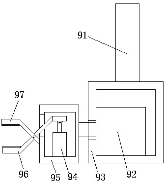
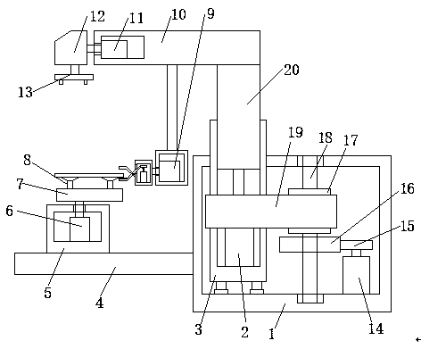
[0020] Embodiment: the wafer is placed on the suction cup 8 on the eccentric wheel 7, the suction cup 8 fixes the eccentric wheel 7, the first motor 6 drives the eccentric wheel 7 to rotate, the eccentric wheel 7 drives the wafer to perform eccentric movement, and the wafer is rotating At the same time, one end of it repeatedly passes through the middle position of the fixed splint 97 and the movable splint 96. When it needs to be flipped, the second cylinder 94 is controlled to drive the movable splint 96 to move, and the wafer is clamped in cooperation with the fixed splint 97. The first cylinder 2 drives the second connecting arm 20 and the cross bar 10 to rise, and the cross bar 10 drives the flip clamping device 9 to rise. After reaching a certain height, the third motor 92 drives the clamp box to rotate 180 degrees to flip the wafer. After the overturn is completed, the first cylinder 2 drives the second connecting arm 20 and the cross bar 10 to descend, the cross bar 10 ...


PUM


Abstract

The invention discloses a wafer scanning and cleaning swing arm device, which comprises a first casing and a support plate, a support plate is welded on the side wall of the first casing, a fixing seat is provided on the top of the support plate, and a fixing seat is provided on the top of the fixing seat. There is a first motor inside, the output shaft of the first motor is connected to an eccentric wheel, and three suction cups are attached to the top of the eccentric wheel, and a first connecting arm is arranged inside the first housing, and the first connecting arm is connected to the first shell The body is flexibly connected, the top of the first connecting arm extends to the top of the first housing, the top of the first connecting arm has a first groove, and the first cylinder is installed on the bottom side wall of the first groove. The piston rod of the air cylinder is welded with a second connecting arm, and the second connecting arm is slidably connected with the side wall of the first groove. The invention can clean both sides of the wafer, is convenient and quick to turn over, does not need manual operation, can scan and clean the wafer from multiple angles, has good cleaning effect and high working efficiency.

Description

technical field [0001] The invention relates to the technical field of wafer cleaning, in particular to a wafer scanning and cleaning swing arm device. Background technique [0002] Generally speaking, in the entire process of chip production, up to 20% of the steps are wafer cleaning. There are four common types of pollution on the wafer surface: fine particles, organic residues, inorganic residues, oxide layers that need to be removed, crystal The purpose of round cleaning is to remove organic compounds, metal impurities or fine particles attached to the surface of the wafer, and the oxide layer that needs to be removed. A wafer scanning and cleaning swing arm device is proposed in the patent CN104810310A, which solves the problem of When cleaning, the cleaning effect is poor, and there is a problem of cleaning dead angles, but it can only clean one side of the wafer, which requires manual flipping, which is inconvenient to clean, and it is inconvenient to adjust the clean...

Claims


Application Information

Patent Timeline
Patent Type & Authority Patents(China)
IPC IPC(8): H01L21/67H01L21/68H01L21/683
CPCH01L21/67023H01L21/67253H01L21/68H01L21/6838
Inventor 李支峰李珍芳
Owner ANHUI TIANYU AUTO PARTS MFG
Learn More