Eureka AIR delivers breakthrough ideas for toughest innovation challenges, trusted by R&D personnel around the world.

A combiner placement support assembly

A combiner and assembly technology, applied in circuits, waveguide-type devices, electrical components, etc., can solve the problems of collision and impact of combiner placement, and achieve the effect of getting rid of installation restrictions, wide application scope, and convenient installation.

Active Publication Date: 2019-07-05
ANHUI ZHONGRUI COMM TECH DEV
View PDF5 Cites 0 Cited by
  • Summary
  • Abstract
  • Description
  • Claims
  • Application Information

AI Technical Summary

Problems solved by technology

[0003] The purpose of the present invention is to overcome the above problems existing in the prior art, to provide a support assembly for placement of a combiner, which solves the problem of placement collision and impact of the combiner

Method used


Image

  • A combiner placement support assembly
  • A combiner placement support assembly
  • A combiner placement support assembly

Examples


Embodiment Construction

[0021] The present invention will be described in detail below with reference to the accompanying drawings and in combination with embodiments.

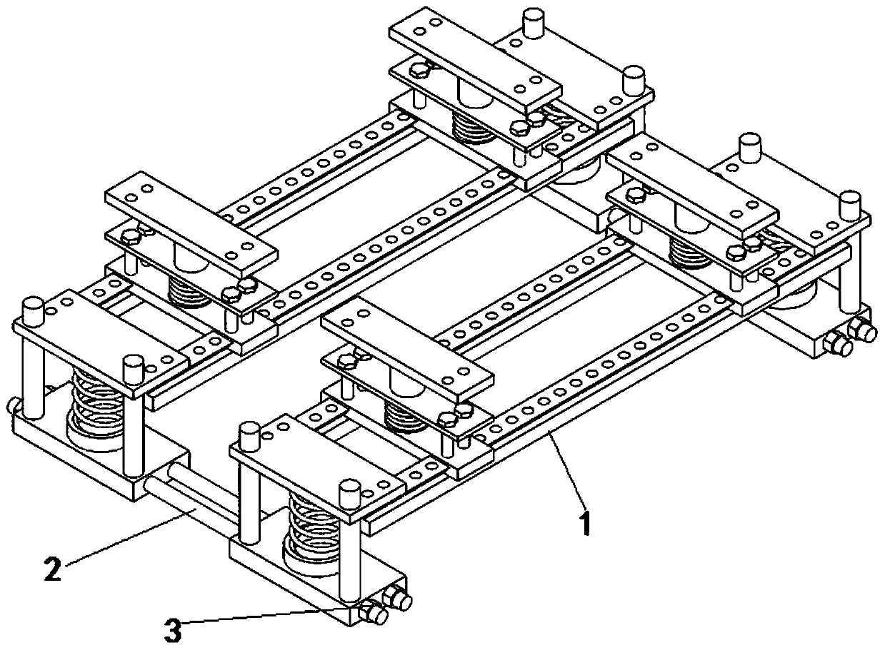
[0022] Such as Figure 1 to Figure 5 The illustrated support assembly for placing a combiner includes two support mechanisms 1, the two support mechanisms 1 are connected by a screw 2, and locknuts 3 are fixed at both ends of the screw 2;

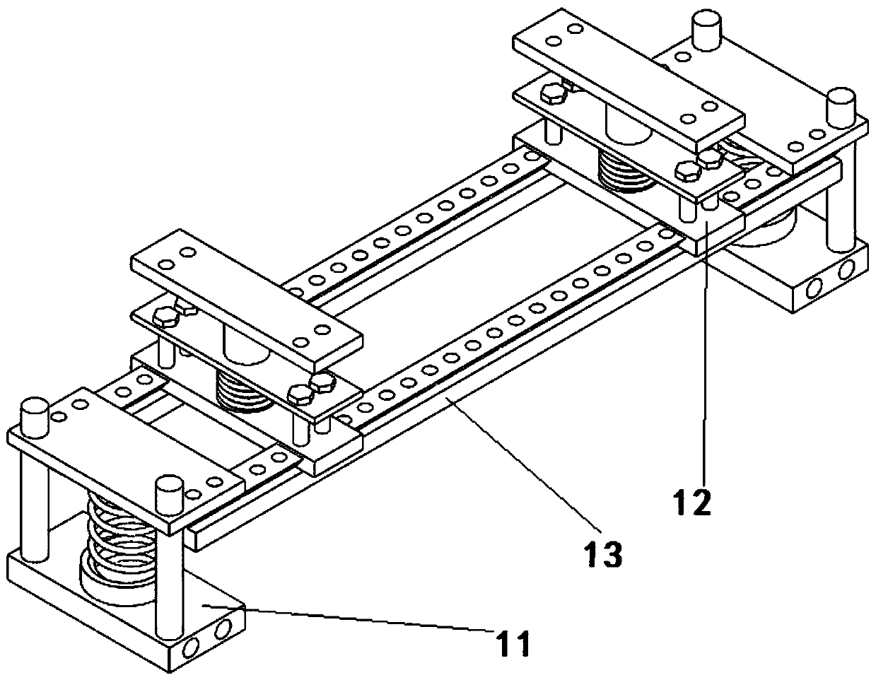
[0023] The support mechanism 1 includes two slide rails 13 parallel to each other, a shock absorbing mechanism 12 is installed on the slide rails 13, and mounting seats 11 are connected to both ends of the slide rails 13;

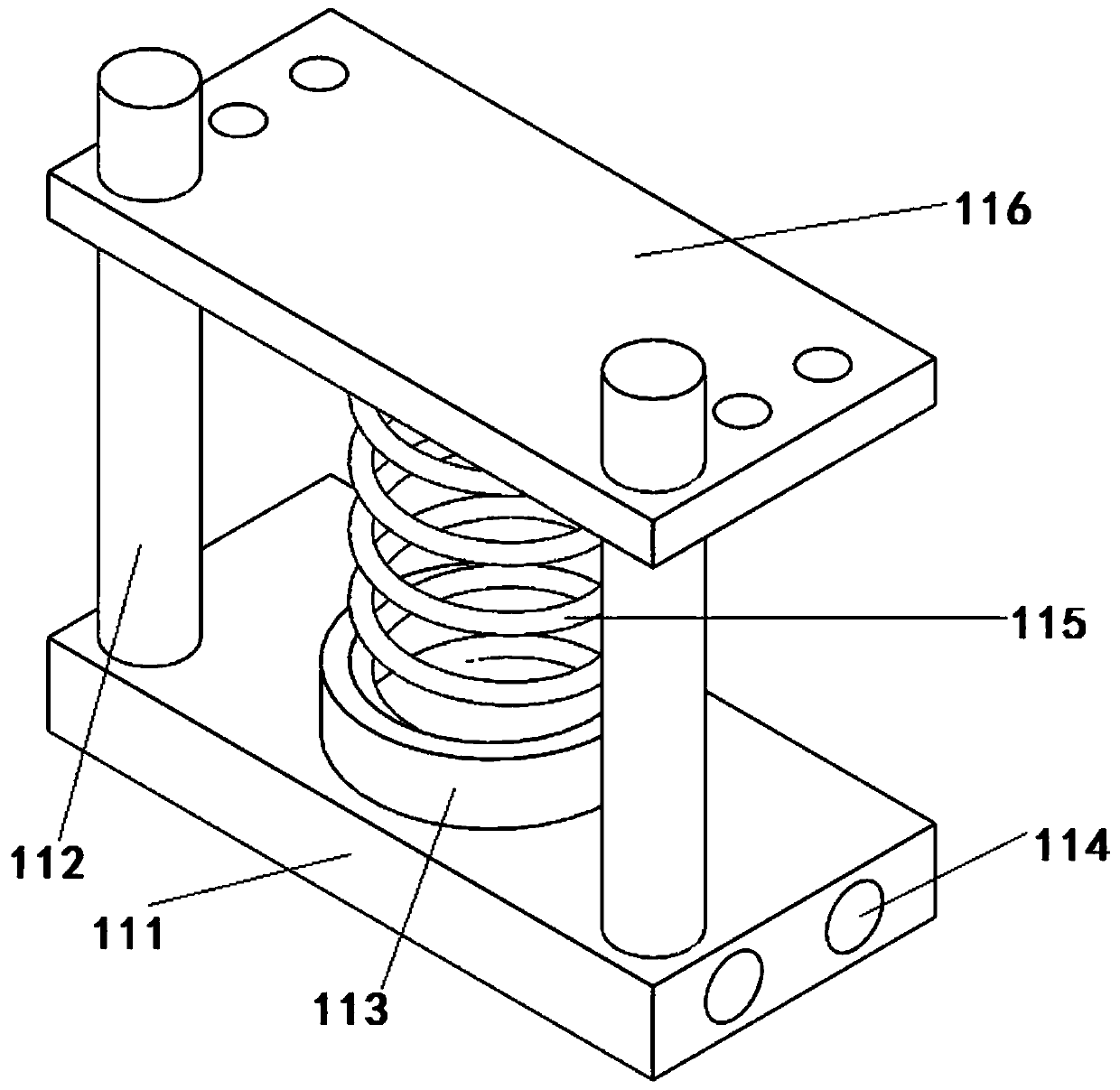
[0024] The mounting seat 11 includes a bottom plate 111, a slide bar 112 is fixed at both ends of the bottom plate 111, a mounting tube 113 is fixed in the center of the surface of the bottom plate 111, a connecting plate 116 is slidably installed on the sliding bar 112, a main spring 115 is installed in the mounting tube 113, and the bottom plate 111 A first threaded hole 114...


PUM


Abstract

The invention discloses a combiner mounting and supporting assembly, comprising two support mechanisms connected through screws; locknuts are fixed to two ends of each screw; each support mechanism includes two slide rails parallel to each other, damping mechanisms are mounted on the slide rails, and mounting seats are connected to two ends of the slide rails; each mounting seat includes a bottom plate, slide rods are fixed to two ends of the bottom plate, a mounting barrel is fixed to the center of the top surface of the bottom plate, a connection plate is slidably mounted on the slide rod , a main spring is mounted in the mounting barrel, and the middle of the bottom plate is provided with a first threaded hole running through the bottom plate; the surface of each slide rail is provided with a slide terrace, and third threaded holes are distributed evenly in the surface of the slide terrace. A combiner is effectively mounted and fixed through the combiner mounting and supporting assembly by the two support mechanisms connected through the screws, and real-time adjustment can be made during installation according to the actual type and size of the combiner; the combiner mounting and supporting assembly is widely applicable, is simple in structure and convenient to mount, is not limited to combiner installation, and is higher in practicality.

Description

technical field [0001] The invention belongs to the field of communication, and in particular relates to a support assembly for placing a combiner. Background technique [0002] In engineering applications, it is necessary to output 800MHZ C network, 900MHz G network or other different frequencies at the same time. Using a combiner, a set of indoor distribution systems can work in the CDMA frequency band, GSM frequency band or other frequency bands at the same time. For example, in the radio antenna system, the input and output signals of several different frequency bands (such as 145MHZ and 435MHZ) are combined by a combiner, and then connected to the radio station with a feeder, which not only saves a feeder, but also avoids switching. The trouble with different antennas. During the use of the traditional combiner, due to the collision and impact of the ground, it will cause certain damage to the internal structure of the combiner, which seriously affects the working perf...

Claims


Application Information

Patent Timeline
Patent Type & Authority Patents(China)
IPC IPC(8): H01P1/213
CPCH01P1/213
Inventor 殷宗成殷敬成
Owner ANHUI ZHONGRUI COMM TECH DEV
Why Eureka
Eureka Blog
Learn More