Barrier-free power supply line erection system for track field

A power supply line, barrier-free technology, applied in the agricultural field, can solve problems such as hindering the use of agricultural machinery and being unable to complete operations.

Inactive Publication Date: 2017-05-31
于光成
View PDF8 Cites 3 Cited by
  • Summary
  • Abstract
  • Description
  • Claims
  • Application Information

AI Technical Summary

Problems solved by technology

[0004] Farmland rails are widely used in the field of agriculture and machinery operations. To realize the automation of the rail field, power supply lines need to be erected in the rail field to meet the energy supply of some agricultural machinery. However, if the power supply line is directly installed in the rail field, it is necessary to Electric poles are erected

Method used


Image

  • Barrier-free power supply line erection system for track field
  • Barrier-free power supply line erection system for track field

Examples


Embodiment Construction

[0011] The invention will be further described below by means of drawings and specific embodiments. The specific embodiments described here are only for explaining the invention, and are not intended to limit the protection scope of the present invention.

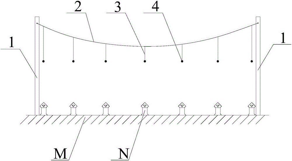
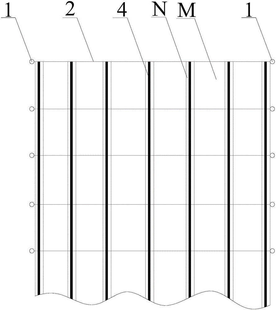
[0012] Rail field barrier-free power supply line erection system, such as figure 1 and figure 2 As shown, several utility poles 1 are included, and the utility poles 1 are evenly supported on both sides of the track field M, and every two utility poles 1 are a group, and a pair of utility poles 1 is erected between the two utility poles 1 of each group. An aerial steel cable 2, the aerial steel cable 2 is perpendicular to the track N of the track field M, and several slings 3 are hoisted under each aerial steel cable 2, and the described sling 3 is located directly above the track N , the lower ends of the slings 3 are on the same horizontal plane, and a power supply line 4 is jointly hoisted at the lower ends of each ro...


PUM


Abstract

The invention provides a barrier-free power supply line erection system for a track field. The barrier-free power supply line erection system comprises a plurality of telegraph poles, wherein the telegraph poles are uniformly erected at two sides of the track field and two telegraph poles are taken as a group; one aerial cable is erected between two telegraph poles in each group and is vertical to tracks of the track field; a plurality of suspension lines are suspended below each aerial cable; a power supply line is suspended at the lower ends of each column of suspension lines; and trends of the power supply lines are parallel to the tracks of the track field. According to the power supply line erection system provided by the invention, the telegraph poles do not need to be erected in the middle of the track field and are replaced with the plurality of aerial cables, and the power supply lines are suspended below the aerial cables, so that the power supply requirements of agricultural machinery can be met and operation of the agricultural machinery is not affected.

Description

technical field [0001] The invention belongs to the technical field of agriculture, in particular to a barrier-free power supply line erecting system for agricultural track fields. Background technique [0002] With the continuous advancement of the process of agricultural mechanization, various agricultural machinery and equipment are also being continuously improved, and more and more farmlands have begun to carry out mechanized farming, sowing, fertilization, spraying and other operations. The traditional operation method is generally done manually, which not only has low operation efficiency and a large amount of manual labor, but sometimes even misses the best operation time due to low operation efficiency, resulting in a large area of ​​crop production reduction. In order to improve operating efficiency and reduce the amount of manual labor, most of the above operations are completed with the help of agricultural machinery. However, due to the structural reasons of ag...

Claims


Application Information

Patent Timeline
IPC IPC(8): H02G7/20
CPCH02G7/20
Inventor 于林于光成
Owner 于光成
Why Eureka
Try Eureka