Television signal receiving device

A technology for receiving devices and TV signals, which is applied in the direction of antenna support/installation device, machine table/bracket, supporting machine, etc., which can solve the extremely strict adjustment of the signal receiver, difficulty in achieving the expected adjustment effect, time-consuming and labor-intensive and other problems, to achieve the effect of reducing labor force, improving installation and maintenance speed, and convenient operation

Active Publication Date: 2017-06-06
SHANDONG LUNENG SOFTWARE TECH
View PDF5 Cites 3 Cited by
  • Summary
  • Abstract
  • Description
  • Claims
  • Application Information

AI Technical Summary

Problems solved by technology

[0002] At present, digital TV has been used in some cities, and in some remote rural areas, the signal quality is poor, and it is often necessary to rely on the TV signal receiver to receive the signal to improve the TV signal quality. They must be set at a certain height to facilitate signal reception. In the prior art, they are usually fixed on poles or roofs, but such a setting method increases the difficulty of installation or maintenance. At the same time, the signal receiver is The adjustment of the angle is extremely strict. It is not only time-consuming and labor-intensive to adjust by manpower, but also the stability of the adjustment is poor and it is difficult to achieve the expected adjustment effect.

Method used


Image

  • Television signal receiving device
  • Television signal receiving device
  • Television signal receiving device

Examples


Embodiment Construction

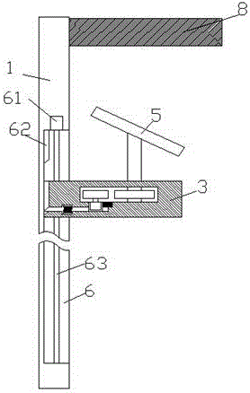
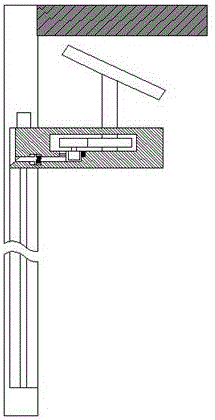
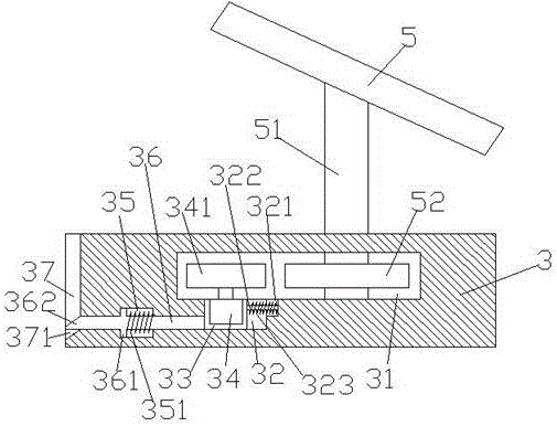
[0018] Such as Figure 1-Figure 5 As shown, a TV signal receiving device of the present invention includes a base 3 that is slidingly fitted and connected to the vertical rod 1 and the vertical rod 1, and the right side of the vertical rod 1 is provided with a sliding cavity 6, and the sliding cavity 6 is arranged on the right side of the vertical rod 1. A screw rod 63 is provided in the shift chamber 6, the top end of the screw rod 63 is connected to the first motor 61, and a bump with a chamfered portion 621 is fixed at the middle end of the top end of the inner wall on the left side of the slide chamber 6 62, the base 3 is set in the sliding cavity 6 and is slidingly fitted, the base 3 is threadedly connected with the screw rod 63, and the top end of the left end surface of the base 3 There is an inserting groove 37 with a chamfered groove 371 for matching with the protrusion 62 at the end, a cavity 31 is set at the middle end of the base 3, and a cavity 31 is set on the ri...


PUM


Abstract

The invention discloses a television signal receiving device. The television signal receiving device comprises a vertical pole and a base which is in sliding fit connection with the vertical pole. A sliding cavity is formed in the inner right side of the vertical pole. A screw rod is arranged in the sliding cavity. The top end of the screw rod is connected with a first motor. A protrusion block with a beveled part is fixedly arranged at the middle end of the top end of the left inner wall of the sliding cavity. The base is arranged in the sliding cavity and is in sliding fit with the sliding cavity. The base and the screw rod are connected through threads in a matched mode. A tight inserting groove provided with a beveled groove is formed in the middle end of the top end of the left end face of the base. A containing cavity is formed in the inner middle end of the base. A rotary pin shaft is arranged on the inner right side of the containing cavity. The top end of the rotary pin shaft penetrates through the base and extends upwards, and the rotary pin shaft is rotationally connected with the base in a matched mode. A signal receiver is obliquely arranged at the top end of the rotary pin shaft. The television signal receiving device is simple in structure and convenient to operate, angle adjustment is easy and convenient, labor force is reduced, and the application efficiency is improved.

Description

technical field [0001] The invention relates to the field of television signal reception, in particular to a television signal reception device. Background technique [0002] At present, digital TV has been used in some cities, and in some remote rural areas, the signal quality is poor, and it is often necessary to rely on the TV signal receiver to receive the signal to improve the TV signal quality. They must be set at a certain height to facilitate signal reception. In the prior art, they are usually fixed on poles or roofs, but such a setting method increases the difficulty of installation or maintenance. At the same time, the signal receiver is The adjustment of the angle is extremely strict, and manual adjustment is not only time-consuming and labor-intensive, but also the stability of the adjustment is poor and it is difficult to achieve the expected adjustment effect. Contents of the invention [0003] The technical problem to be solved by the present invention is ...

Claims


Application Information

Patent Timeline
Patent Type & Authority Applications(China)
IPC IPC(8): F16M11/18F16M11/04H01Q1/12
CPCF16M11/04F16M11/18H01Q1/12
Inventor 刘秋来
Owner SHANDONG LUNENG SOFTWARE TECH
Why Eureka
Try Eureka