
PCB and electronic device

A technology of printed circuit boards and flexible circuit boards, applied in the field of electronics, can solve the problems of increasing costs, consuming PCB production resources, and large PCB area

Pending Publication Date: 2017-06-06
BLACKSHARK TECH NANCHANG CO LTD
View PDF1 Cites 4 Cited by
  • Summary
  • Abstract
  • Description
  • Claims
  • Application Information

AI Technical Summary

Problems solved by technology

[0004] Using the existing technology, the PCB area occupied by the test points is relatively large, which will increase unnecessary costs, consume PCB production resources, and cause an additional burden on the environment. Special test points need to be set on the PCB of electronic equipment for automated testing.

Method used


Image

  • PCB and electronic device
  • PCB and electronic device
  • PCB and electronic device

Examples


Embodiment Construction

[0027] The following will clearly and completely describe the technical solutions in the embodiments of the present invention with reference to the accompanying drawings in the embodiments of the present invention. Obviously, the described embodiments are only some, not all, embodiments of the present invention. Based on the embodiments of the present invention, all other embodiments obtained by persons of ordinary skill in the art without making creative efforts belong to the protection scope of the present invention.

[0028] The terms "first", "second", "third", "fourth", etc. (if any) in the description and claims of the present invention and the above drawings are used to distinguish similar objects, and not necessarily Used to describe a specific sequence or sequence. It is to be understood that the data so used are interchangeable under appropriate circumstances such that the embodiments of the invention described herein - for example - can be practiced in sequences oth...


PUM


Abstract

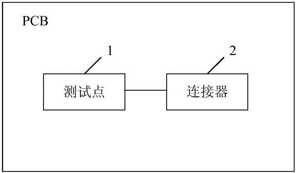
The invention provides a PCB and an electronic device, wherein the PCB includes a test point and a connector. The connector is a device on the PCB and that can be connected with an external cable. The connector is connected to a component to be tested on the PCB. The test point is connected with the component to be tested through the connector. The test point matches a first test tool. The first test tool tests the component via the test point. According to the PCB and the electronic device provided by the invention, the test point is set on the existing connector of the PCB so that it is not necessary to set the test point separately on the PCB, which reduces the PCB area occupied by the test point.

Description

technical field [0001] The invention relates to electronic technology, in particular to a PCB and electronic equipment. Background technique [0002] In the current production process of electronic equipment, multiple tests need to be completed on the production line, and some test items adopt automated test solutions to reduce manpower input and test costs. [0003] In the prior art, during automated testing of electronic equipment, testing is performed by connecting test points set on a printed circuit board (Printed Circuit Board, PCB for short) of the electronic equipment through an automated testing fixture. [0004] Using the existing technology, the PCB area occupied by the test points is relatively large, which will increase unnecessary costs, consume PCB production resources, and cause an additional burden on the environment. Special test points need to be set on the PCB of electronic equipment for automated testing. Contents of the invention [0005] The inventi...

Claims


Application Information

Patent Timeline
IPC IPC(8): G01R31/28H05K1/02
CPCH05K1/0268G01R31/2818H05K2203/16
Inventor 不公告发明人
Owner BLACKSHARK TECH NANCHANG CO LTD
Learn More