Axial fan

A technology of axial flow and fan, applied in axial flow pumps, non-variable pumps, non-displacement pumps, etc., can solve the problem of high operating noise of axial flow fans, achieve the effect of reducing operating noise and suppressing pressure changes

Active Publication Date: 2020-09-22
SUNONWEALTH ELECTRIC MACHINE IND
View PDF10 Cites 0 Cited by
  • Summary
  • Abstract
  • Description
  • Claims
  • Application Information

AI Technical Summary

Problems solved by technology

[0005] The present invention provides an axial flow fan and its fan frame. The axial flow fan can solve the problem of high operating noise of the prior art axial flow fan by means of its fan wheel.

Method used


Image

  • Axial fan
  • Axial fan
  • Axial fan

Examples


Embodiment Construction

[0047] In order to make the above and other objects, features and advantages of the present invention more comprehensible, preferred embodiments of the present invention will be described in detail below together with the accompanying drawings.

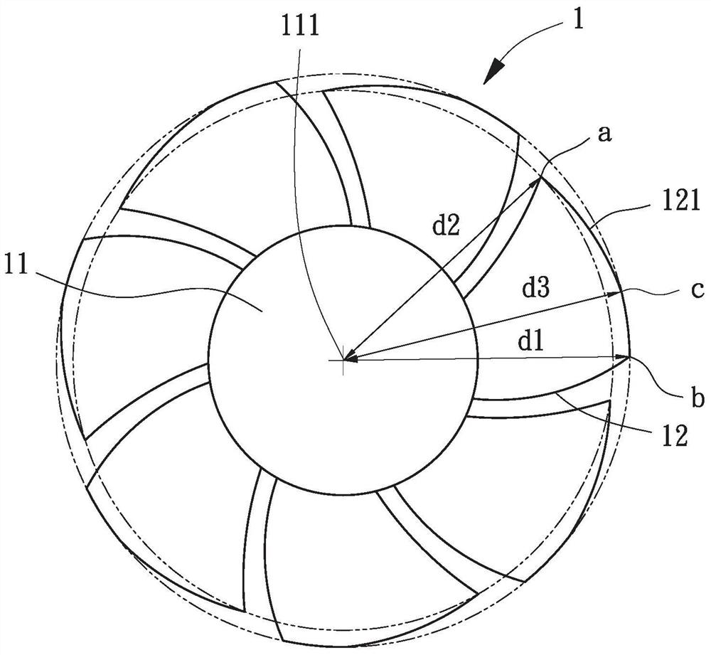
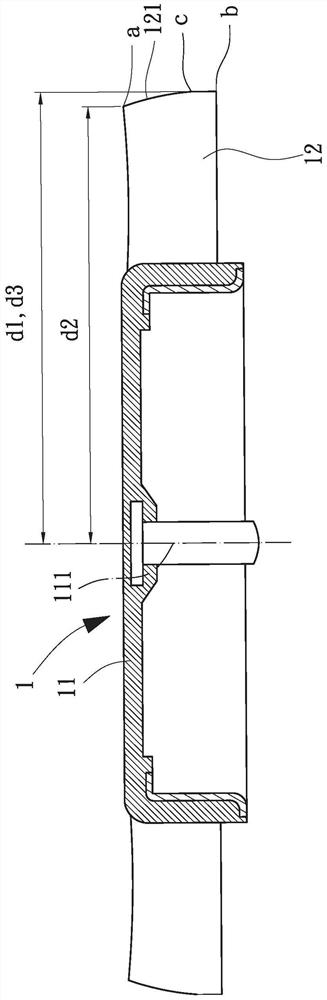
[0048] Please refer to figure 2 and 3 Shown is the fan wheel 1 of an embodiment of the axial flow fan of the present invention, the fan wheel 1 includes a hub 11 and several fan blades 12, and the several fan blades 12 are connected to the hub 11. The hub 11 has a rotation axis 111 , the rotation axis 111 is parallel to the axial direction of the fan wheel 1 , and the rotation axis 111 passes through the center of the hub 11 . Each fan blade 12 is inclined to the axial direction of the fan wheel 1, and each fan blade 12 has an outer edge 121 in the radial direction of the fan wheel 1, and the outer edge 121 is located where the fan blade 12 is far away from the hub 11. side. The two ends of the outer edge 121 in the axial directio...


PUM


Abstract

The invention provides an axial flow type fan and fan wheel thereof for the higher problem of axial flow fan running noise is commonly used in the solution. This axial flow fan's impeller contains a wheel hub and several flabellum. This wheel hub has a rotation axis. The several flabellum combines in abovementioned wheel hub, and respectively this flabellum upwards has a lateral border in the footpath of this impeller, and this lateral border is an inlet air extreme point and an air-out extreme point at the ascending both ends of axle of this impeller. Wherein, abovementioned lateral border more has a convergent and plays the initial point, and the distance that this convergent plays the supreme rotation axis of stating of initial point is greater than the distance of above -mentioned inlet air extreme point to this rotation axis.

Description

technical field [0001] The invention relates to an axial flow fan and its fan wheel, in particular to an axial flow fan capable of reducing fan noise. Background technique [0002] Please refer to figure 1 A prior art axial flow fan 9 shown includes a fixed assembly 91 and a rotating assembly 92 . The fixing component 91 includes a fan frame 91 a, the fan frame 91 a has a side wall 911 , and the side wall 911 surrounds and forms a wind driving channel 912 for accommodating the rotating component 92 . The rotating assembly 92 has a fan wheel 92a, the fan wheel 92a includes a hub 921 and a plurality of fan blades 922, and in the radial direction of the fan wheel 92a, each fan blade 922 has an inner edge 922a and an outer edge 922b, the inner edge 922a is combined with the hub 921, the outer edge 922b is adjacent to the side wall 911, and the distance from any position of the outer edge 922b to the center of the hub 921 of the fan wheel 92a remains substantially constant. Ac...

Claims


Application Information

Patent Timeline
Patent Type & Authority Patents(China)
IPC IPC(8): F04D29/32F04D29/38F04D29/66F04D25/02F04D19/00
Inventor 洪银树李承熹
Owner SUNONWEALTH ELECTRIC MACHINE IND
Why Eureka
Try Eureka