Dehumidification method capable of eliminating white smoke phenomena at return air shaft mouths

A return air shaft, air flow dehumidification technology, applied in separation methods, chemical instruments and methods, gas treatment, etc., can solve the problems of difficult maintenance and management, high construction risk, and low atomization degree in the later stage, so as to facilitate later maintenance and management, Effect of eliminating visual pollution and high dehumidification efficiency

Active Publication Date: 2017-06-13
SINOSTEEL MAANSHAN INST OF MINING RES
View PDF9 Cites 5 Cited by
  • Summary
  • Abstract
  • Description
  • Claims
  • Application Information

AI Technical Summary

Problems solved by technology

[0008] The purpose of the present invention is to solve the visual pollution phenomenon of "white smoke" at the wellhead formed by high-temperature saturated air in the return air shaft of the mine, and the existing technical solutions have low atomization degree, poor defogging effect, high ventilation energy consumption, and high construction risk. In order to solve technical problems such as difficult maintenance and management in the later period, it provides a dehumidification method with sufficient atomization, high demisting efficiency, low ventilation energy consumption, and can be changed according to air temperature and air volume, which can eliminate the phenomenon of white smoke at the return air wellhead

Method used


Image

  • Dehumidification method capable of eliminating white smoke phenomena at return air shaft mouths
  • Dehumidification method capable of eliminating white smoke phenomena at return air shaft mouths

Examples


Embodiment Construction

[0028] In order to further describe the present invention, a dehumidification method of the present invention capable of eliminating the phenomenon of white smoke at the wellhead of the return air will be further described in detail below in conjunction with the accompanying drawings and examples.

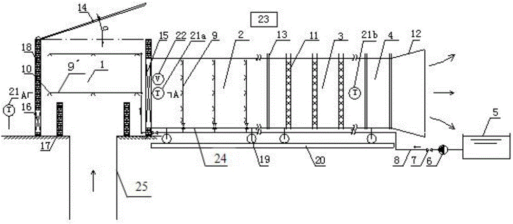
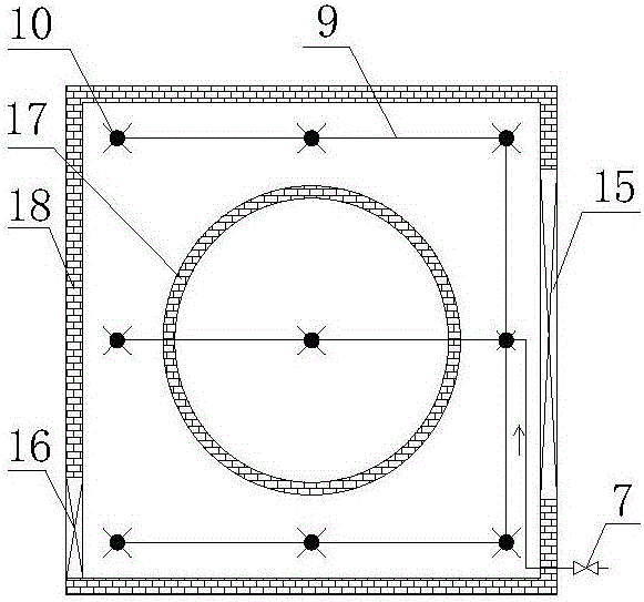
[0029] Have figure 1 The schematic diagram of the structural layout of the high-temperature saturated air flow dehumidification device adopted by the present invention is shown in conjunction with figure 2 It can be seen that the high-temperature saturated air flow dehumidification device adopted in a dehumidification method capable of eliminating the white smog phenomenon at the return air wellhead of the present invention is composed of a spray cooling system, a confluence area 1, an atomization area 2, a dehumidification area 3, and an outflow area 4 , sensors, and a PLC control system 23 connected to the sensors; the confluence area 1 is arranged above the shaft 1 of the retur...


PUM


Abstract

The invention discloses a dehumidification method capable of eliminating white smoke phenomena at return air shaft mouths. The dehumidification method is implemented by a high-temperature saturated wind current dehumidification device. The high-temperature saturated wind current dehumidification device comprises a confluence zone (1), an atomization zone (2), a dehumidification zone (3), a current discharge zone (4), rollers (19) and a guide rail (20). A cover plate (14) is mounted on the top of the confluence zone (1), an electric gate (15) is mounted on a side surface of the confluence zone (1), and an atmosphere temperature sensor (21) is mounted outside the confluence zone (1); a hot-air temperature sensor (21a) and a wind speed sensor (22) are mounted at an inlet of the atomization zone (2); the dehumidification zone (3) is provided with filter screens (11), and a dehumidified air temperature sensor (21b) is mounted at an outlet of the dehumidification zone (3); the cover plate (14), the electric gate (15), an electric valve (7) and a spray pump (6) are controlled by a PLC (programmable logic control) system (23). The dehumidification method has the advantages of structure optimization, sufficient atomization, high defogging efficiency and low ventilation energy consumption. Besides, dehumidification can be carried out as needed according to requirements of change of wind temperatures and wind volumes.

Description

technical field [0001] The invention belongs to the technical field of mine ventilation and environmental protection, and in particular relates to a dehumidification method for condensing and dewing the high-temperature saturated air flow in an underground mine return air shaft and avoiding the phenomenon of "white smoke" at the well head. Background technique [0002] The fresh air of the mine ventilation system enters from the surface along the air intake shaft, and exchanges heat and moisture with various heat and humidity sources such as underground mining machinery and equipment, damp surrounding rock walls, and ore self-oxidation, which gradually increases the temperature and humidity of the underground air. Generally, the relative humidity of the underground air in the mine is close to 100% saturated, and the air temperature in the mine is close to the dew point temperature. As long as the ambient temperature is lower than the air temperature in the mine, the water vap...

Claims


Application Information

Patent Timeline
Patent Type & Authority Applications(China)
IPC IPC(8): B01D53/26
CPCB01D53/265B01D2257/80
Inventor 黄寿元贾敏涛李刚周伟居伟伟李玲玲吴冷峻贾安民
Owner SINOSTEEL MAANSHAN INST OF MINING RES
Why Eureka
Try Eureka