Underground mine return air shaft high temperature saturated air flow dehumidification device and method

A technology for air flow dehumidification and return air shaft, which is applied to the device for eliminating water mist at the wellhead, and the field of mine return air shaft air flow dehumidification on demand. It can solve the problems of difficult maintenance and management, high construction risk, and high ventilation energy consumption in the later stage, so as to facilitate the later Maintenance management, elimination of visual pollution, good visual effects

Active Publication Date: 2018-09-18
SINOSTEEL MAANSHAN INST OF MINING RES +1
View PDF8 Cites 0 Cited by
  • Summary
  • Abstract
  • Description
  • Claims
  • Application Information

AI Technical Summary

Problems solved by technology

[0008] The purpose of the present invention is to solve the visual pollution phenomenon of "white smoke" at the wellhead formed by high-temperature saturated air in the return air shaft of the mine, and the existing technical solutions have low atomization degree, poor defogging effect, high ventilation energy consumption, and high construction risk. In order to solve technical problems such as difficult maintenance and management in the later stage, a high-temperature saturated air flow dehumidification device for underground mine return air shafts with optimized structure, sufficient atomization, high demisting efficiency, low ventilation energy consumption, and variable air temperature and air volume can be provided.

Method used


Image

  • Underground mine return air shaft high temperature saturated air flow dehumidification device and method
  • Underground mine return air shaft high temperature saturated air flow dehumidification device and method

Examples


Embodiment Construction

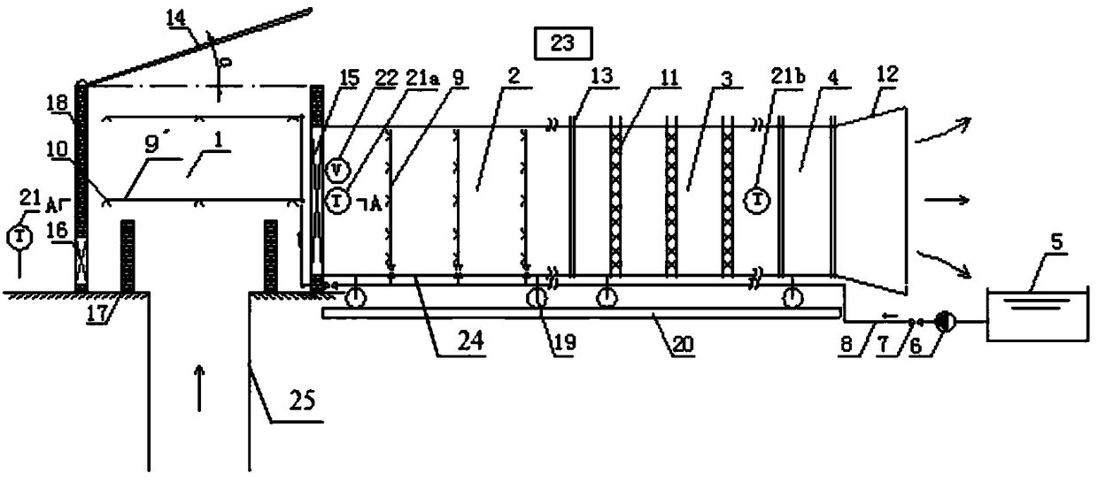
[0028]In order to further describe the present invention, the high-temperature saturated air flow dehumidification device and method of the underground mine return air shaft of the present invention will be further described in detail below in conjunction with the accompanying drawings and embodiments.

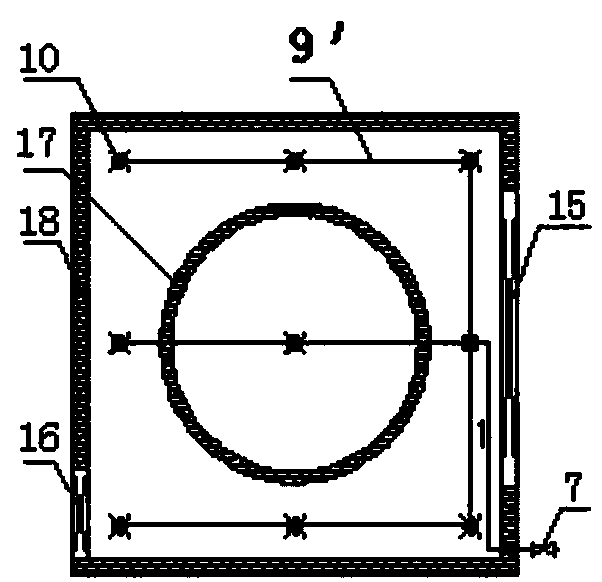
[0029] have figure 1 The schematic diagram of the structural arrangement of the high-temperature saturated air flow dehumidification device of the underground mine return air shaft of the present invention shown and combined figure 2 It can be seen that the high-temperature saturated air flow dehumidification device of the underground mine return air shaft of the present invention is composed of a spray cooling system, a confluence area 1, an atomization area 2, a dehumidification area 3, an outflow area 4, a sensor and a PLC control system 23 connected with the sensor Combination; the confluence area 1 is arranged above the shaft 25 of the return air shaft, and the confluenc...


PUM


Abstract

The invention discloses a dehumidifying device and method for an underground mine return-air shaft high-pressure saturated airflow. The device comprises a confluent area (1), an atomization area (2), a dehumidifying area (3), an outflow area (4), rollers (19) and a guide rail (20). A cover plate (14) is arranged on the top of the confluent area (1), an electric gate (15) is mounted on the side face of the confluent area (1), and an atmospheric temperature sensor (21) is mounted on the outer side of the confluent area (1). A hot air temperature sensor (21a) and a wind speed sensor (22) are mounted at an inlet of the atomization area (2). Filtering nets (11) are mounted in the dehumidifying area (3), and dehumidified air temperature sensor (21b) is mounted at an outlet of the dehumidifying area (3). A diffuser (12) is arranged at an outlet of the outflow area (4). A PLC control system (23) controls the cover plate (14), the electric gate (15), an electric valve (7), and a spraying pump (6). The dehumidifying device has the advantages of optimized structure, full atomization, high demisting efficiency and low ventilation energy consumption, and on-demand dehumidifying according to the change of the air temperature and air amount is achieved.

Description

technical field [0001] The invention belongs to the technical field of mine ventilation and environmental protection, and specifically relates to a dehumidification device and method for making the high-temperature saturated air flow condense and condense in the return air shaft of an underground mine and avoiding the phenomenon of "white smoke" at the well head, and is especially suitable for the return air shaft of a deep underground mine. A device and method for dehumidifying and eliminating water mist at the wellhead by wind flow in mine return air wells with high air flow temperature and low surface atmospheric temperature. Background technique [0002] The fresh air of the mine ventilation system enters from the surface along the air intake shaft, and exchanges heat and moisture with various heat and humidity sources such as underground mining machinery and equipment, damp surrounding rock walls, and ore self-oxidation, which gradually increases the temperature and humi...

Claims


Application Information

Patent Timeline
Patent Type & Authority Patents(China)
IPC IPC(8): E21F3/00
CPCE21F3/00
Inventor 黄寿元李刚贾敏涛居伟伟周伟蔡建华贾安民吴冷峻
Owner SINOSTEEL MAANSHAN INST OF MINING RES
Why Eureka
Try Eureka