Steel plate bending equipment for hardware production

A kind of function and steel plate technology, applied in the field of steel plate bending equipment, can solve the problems of unsatisfactory bending effect, low bending efficiency, high manual labor intensity, etc., and achieve the effect of reducing manual labor intensity, improving efficiency, and ideal bending effect

Inactive Publication Date: 2018-08-21
唐山国义特种钢铁有限公司
View PDF6 Cites 4 Cited by
  • Summary
  • Abstract
  • Description
  • Claims
  • Application Information

AI Technical Summary

Problems solved by technology

During the processing of hardware, it is often necessary to bend it in order to bend it into a shape that meets the requirements. The existing bending operations often use manual bending. Manual bending is not only low in efficiency and poor in bending effect, but also labor-intensive. Although Some steel plate bending devices have appeared, but the bending effect is not ideal, the bending efficiency is low, and it cannot effectively meet the needs of metal processing

Method used


Image

  • Steel plate bending equipment for hardware production

Examples


Embodiment Construction

[0018] The steel plate bending equipment for hardware production of the present invention will be clearly and completely described below in conjunction with the accompanying drawings.

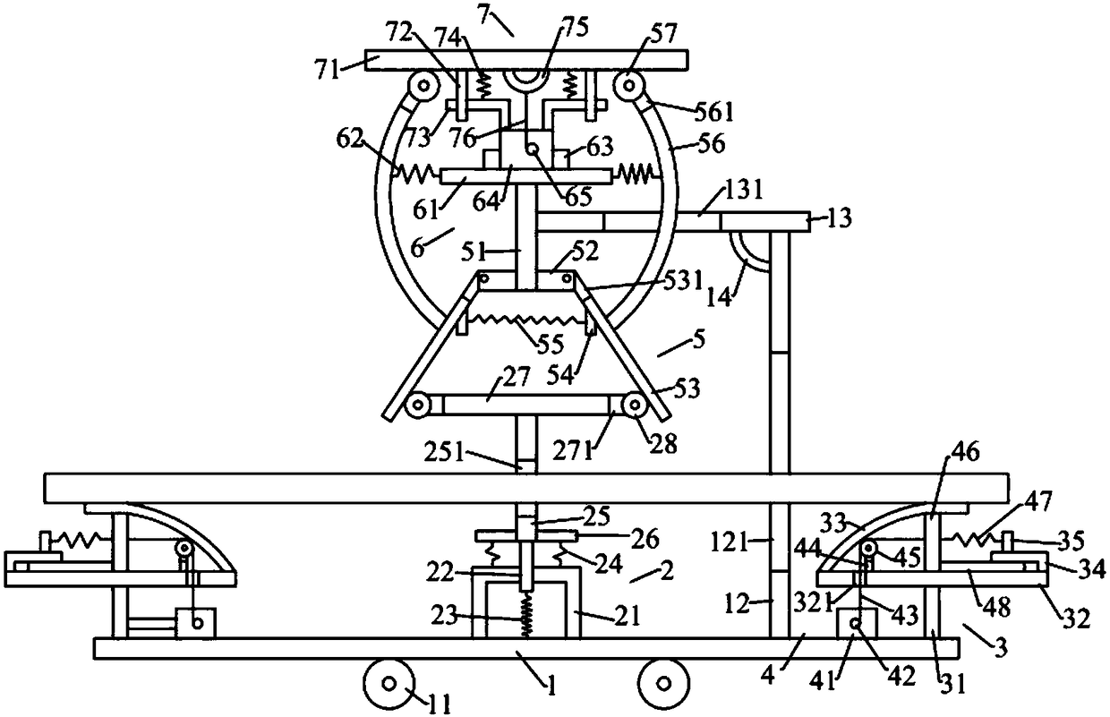
[0019] Such as figure 1 As shown, the steel plate bending equipment for hardware production of the present invention includes a base plate 1, a first extruding device 2 located above the base plate 1, and a second extruding device 3 located on the left and right sides of the first extruding device 2 , the first pushing device 4 arranged on the second pressing device 3, the second pushing device 5 positioned above the first pressing device 2, the motor device 6 arranged on the second pushing device 5 And the abutment device 7 located above the motor device 6 .

[0020] Such as figure 1As shown, the bottom plate 1 is rectangular parallelepiped and is placed horizontally. The bottom plate 1 is provided with a universal wheel 11 below it, a first support rod 12 above it, and a first support rod 1...


PUM


Abstract

Efficient plate bending equipment for hardware manufacture comprises a bottom plate, a first extrusion unit, a second extrusion unit, a first pushing unit, a second pushing unit, a motor unit and an abutting unit; the bottom plate is provided with universal wheels, a first support rod, a first fixing rod and a second fixing rod; the first extrusion unit comprises a first positioning rack, a first vertical rod, a first spring, a first extrusion plate, a first transverse rod, second springs, a second transverse rod, and first rollers; the second extrusion unit includes a second support rod, a second transverse late, a second extrusion plate, a second positioning rack, and a second vertical rod; the first pushing unit includes a first motor, a first output shaft, a first pull wire, a third vertical rod, a second roller, a first pushing rod, and a third spring; the second pushing unit includes a fourth vertical rod, first fixing blocks, rotating rods, and third fixing rods. The efficient plate bending equipment for hardware manufacture can provide effective bending for a steel plate, and the middle and ends of the steel plate are extruded at the same time so that bending efficiency is improved effectively.

Description

technical field [0001] The invention relates to the technical field of steel plate bending, in particular to a steel plate bending equipment for hardware production. Background technique [0002] The so-called hardware in modern society includes hardware tools, hardware parts, daily hardware, construction hardware and so on. During the processing of hardware, it is often necessary to bend it in order to bend it into a shape that meets the requirements. The existing bending operations often use manual bending. Manual bending is not only inefficient, but also has a poor bending effect, and the labor intensity is high. Although Some steel plate bending devices have appeared, but the bending effect is not ideal, the bending efficiency is low, and it cannot effectively meet the needs of metal processing. [0003] Therefore, it is necessary to provide a new technical solution to overcome the above defects. Contents of the invention [0004] The object of the present invention ...

Claims


Application Information

Patent Timeline
Patent Type & Authority Patents(China)
IPC IPC(8): B21D5/01B21D43/00
CPCB21D5/002B21D5/01
Inventor 吴振彪
Owner 唐山国义特种钢铁有限公司
Why Eureka
Try Eureka