Drainage device capable of regulating drainage area

An adjustable and regional technology, applied in suction devices, hypodermic injection devices, extraction and pumping systems, etc., can solve the problems of organ damage, limited adsorption range, poor drainage effect, etc., and achieve low cost and high economic benefits. Effect

Pending Publication Date: 2019-07-19
JIANGYIN PEOPLES HOSPITAL
View PDF0 Cites 2 Cited by
  • Summary
  • Abstract
  • Description
  • Claims
  • Application Information

AI Technical Summary

Problems solved by technology

[0005] 1) The drainage tube in the prior art is cylindrical, and its adsorption range is limited after entering the body cavity of the human body, resulting in poor drainage effect;
[0006] 2) The draina

Method used


Image

  • Drainage device capable of regulating drainage area
  • Drainage device capable of regulating drainage area
  • Drainage device capable of regulating drainage area

Examples


Embodiment 1

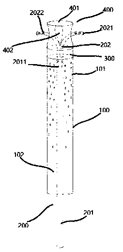
[0057] Please refer to figure 1 , 2 In this embodiment, the adjusting tube 401 at least includes:

[0058] Side wall; and

[0059] Blind end 4013, both ends of the blind end 4013 are fixedly connected with the side wall, and the bottom surface of the blind end 4013 is fixedly connected with an adjusting member 402.

[0060] At the same time, it should be noted that the user can increase / decrease the number of branches according to the number of bifurcated ends, so as to effectively make the bifurcated ends pass through the space formed between the respective branches, so that the bifurcated ends are in different areas , So as to carry out negative pressure drainage to different areas.

Embodiment 2

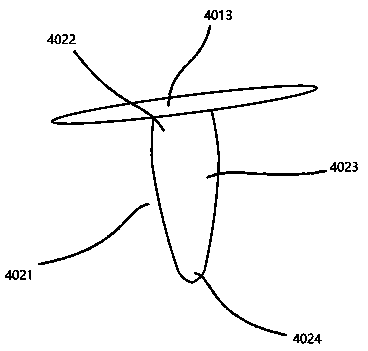
[0062] Please refer to figure 1 , 2 In this embodiment, the adjusting component 402 is an adjusting block 4021, and the top end of the adjusting block 4021 is fixedly connected to the bottom surface of the blind end 4013.

[0063] The adjusting block 4021 is divided into a top section 4022, a middle section 4023, and a bottom section 4024 from top to bottom; the bottom section 4024 has a smaller cross-sectional diameter than the middle section 4023; one end of the top section away from the middle section 4023 and a blind end The bottom surface of 4013 is fixedly connected. When in use, the lower part of the bottom section 4024 is the bifurcation structure 202. When the user pushes the inner tube 201, the bottom section 4024 contacts the bifurcation ends 2021 of the bifurcation structure 202, and the user continues to push the inner tube 201, thereby The bottom section 4024 is inserted into each of the bifurcated ends 2021. Since the cross-sectional diameter of the middle section 4...

Embodiment 3

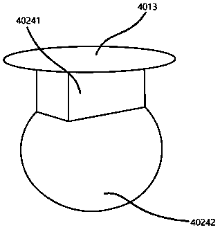
[0065] Please refer to image 3 In this embodiment, the adjusting component 402 is an airbag member 4124, and one end of the airbag member 4124 is fixedly connected to the bottom surface of the blind end 4013.

[0066] The airbag component 4124 includes:

[0067] An airbag seat 40241, one end of which is fixedly connected to the bottom surface of the blind end 4013; and

[0068] The airbag 40242 is installed at the bottom end of the airbag seat 40241, and the installation method of the airbag 40242 and the airbag seat 40241 is common in the prior art; and

[0069] Inflatable tube, one end of the inflatable tube passes through the outer sleeve 100 in turn, the connecting through hole is connected with the airbag seat 40241, and the other end is connected with the inflator.


PUM


Abstract

The present invention discloses a drainage device capable of adjusting a drainage area. The drainage device comprises an outer sleeve pipe and also comprises an inner sleeve pipe structure, a connection structure and a suction adjustment structure; a plurality of drainage holes are arranged in an outer circumference of the outer sleeve pipe, the inner sleeve pipe structure comprises an inner pipeand a bifurcation structure; the suction adjustment structure is connected with a top end of the connection structure; the suction adjustment structure comprises a bracket, a bottom end of the bracketis fixedly connected with the top end of the connection structure, the bracket is provided with a space for passing out of bifurcation ends and an adjustment member, and the adjustment member is fixedly arranged on the bracket and contacts with the bifurcation structure to press the bifurcation ends. By arranging the inner sleeve pipe structure, the drainage device in human body can also conductdrainage of liquid near bifurcation suction holes in the bifurcation ends by the bifurcation structure in the inner sleeve pipe structure; and users only need to push the inner pipe, so that the adjustment member of the suction adjustment structure contacts and presses the bifurcation ends to conduct drainage of different areas in body cavities.

Description

Technical field [0001] The invention relates to the technical field of medical drainage equipment, in particular to a drainage device with an adjustable drainage area. Background technique [0002] In medical clinics, in order to prevent postoperative infections and promote postoperative wound healing, it is often necessary to apply a drainage tube device to a patient after surgery. It can remove pus, blood and fluid in the body tissue or body cavity. And so on to the body. Drainage tube devices are used in multiple post-operations, including chest cavity, brain cavity, gastrointestinal tract, biliary tract, etc. [0003] Most of the drainage tubes in the prior art are cylindrical and tubular structures with drainage holes on the outer circumference, which are inserted into the patient's body during use, and negative pressure is connected to the drainage tube, so that the pus, blood and liquid in the body cavity are drained The hole is led out of the body. [0004] However, in the...

Claims


Application Information

Patent Timeline
IPC IPC(8): A61M1/00
CPCA61M1/0023A61M1/74A61M1/84
Inventor 冯智华潘春芳严娜萍
Owner JIANGYIN PEOPLES HOSPITAL
Why Eureka
Try Eureka