Roll, Rolling Mill and Rolling Method

a technology of rolling mill and rolling mill, which is applied in the direction of manufacturing tools, counter-pressure devices, and profile control devices, etc., can solve the problems of reducing affecting the accuracy of rolling, so as to reduce the edge drop, and improve the accuracy of rolling

Active Publication Date: 2009-09-03
JP STEEL PLANTECH
View PDF3 Cites 2 Cited by
  • Summary
  • Abstract
  • Description
  • Claims
  • Application Information

AI Technical Summary

Benefits of technology

[0033]By the action of the rolls mentioned above, the rolling mill can properly correct the plate crown and reduce the edge drop. Further the roll bending can be effectively executed; therefore the rolling mill has a considerably high capability of correcting the plate crown. Since the inconvenient increase of the line contacting pressure with other rolls is avoidable, damage to the roll due to spalling etc. hardly occurs.
[0034]Regarding such a rolling mill, particularly it is preferable that the roll is disposed as a pair of work-rolls. Because by forming the roll crown on the work-roll which contacts with a material to be rolled, the work-roll can directly exert the function of correcting the plate crown and of reducing the edge drop on the material to be rolled and bring about the remarkable effects. Even when the rolling load is small, the function acts easily too.
[0035]Otherwise, it is also preferable that the roll is disposed as a pair of intermediate rolls. In this case also, the rolling mill has the proper roll gap formed between the work-rolls according to the roll crown of the roll and further has the part of the enlarged gap where the constraining force is loosened, thereby exerting the function of correcting the plate crown and reducing the edge drop. In the case where the roll is disposed as the intermediate roll like this, further advantageously the roll bending can be effectively exerted on the work-roll.
[0036]It should be noted that the roll can be disposed also as a pair of backup rolls. This case also has the same merits as described above and in particular further has the following effect: since a flat and plane roll can be used as the work-roll, the surface properties of a material to be rolled is easily heightened; therefore it is easy to answer the required quality as a four-high mill for aluminum plate and raw tinplate and other mills. Moreover, since the roll is generally applied to the backup roll of a four-high mill, advantageously the number of rolls is less than that of a six-high mill.

Problems solved by technology

The arts in the patent bibliographies 1 and 2 may correct the plate crown through the action by the roll crown, but will not correct the plate edge state such as the edge-drop (a phenomenon in the plate that the edge hangs down to lose the corner and the plate thickness becomes thinner.)
In addition, when backup rolls are used, the end part of the work-rolls are in contact with, and constrained by, the backup rolls, therefore, it is impossible to correct the plate crown by exerting a strong roll bending.
Moreover, since one end of the S-shaped roll crown has a part of increasing roll diameter (the part shown as # of FIG. 8), the line contacting pressure against the backup rolls in a four-high mill or a six-high mill may increase excessively to cause a local spalling etc. which may damage the roll and shorten the roll life.
The art of the patent bibliography 3 or 4 can effectively bend the roll because the end of the roll is not constrained, however, when rolling, the intermediate roll and other rolls are in contact with each other in a short range to cause the increase of the line pressure between rolls; as a result, it is predicted that the roll damage such as spalling easily occurs.
When a roll crown is not provided (the cited bibliography 3), disadvantageously the capability of correcting the plate crown is not sufficiently performed.

Method used


Image

  • Roll, Rolling Mill and Rolling Method
  • Roll, Rolling Mill and Rolling Method
  • Roll, Rolling Mill and Rolling Method

Examples


example

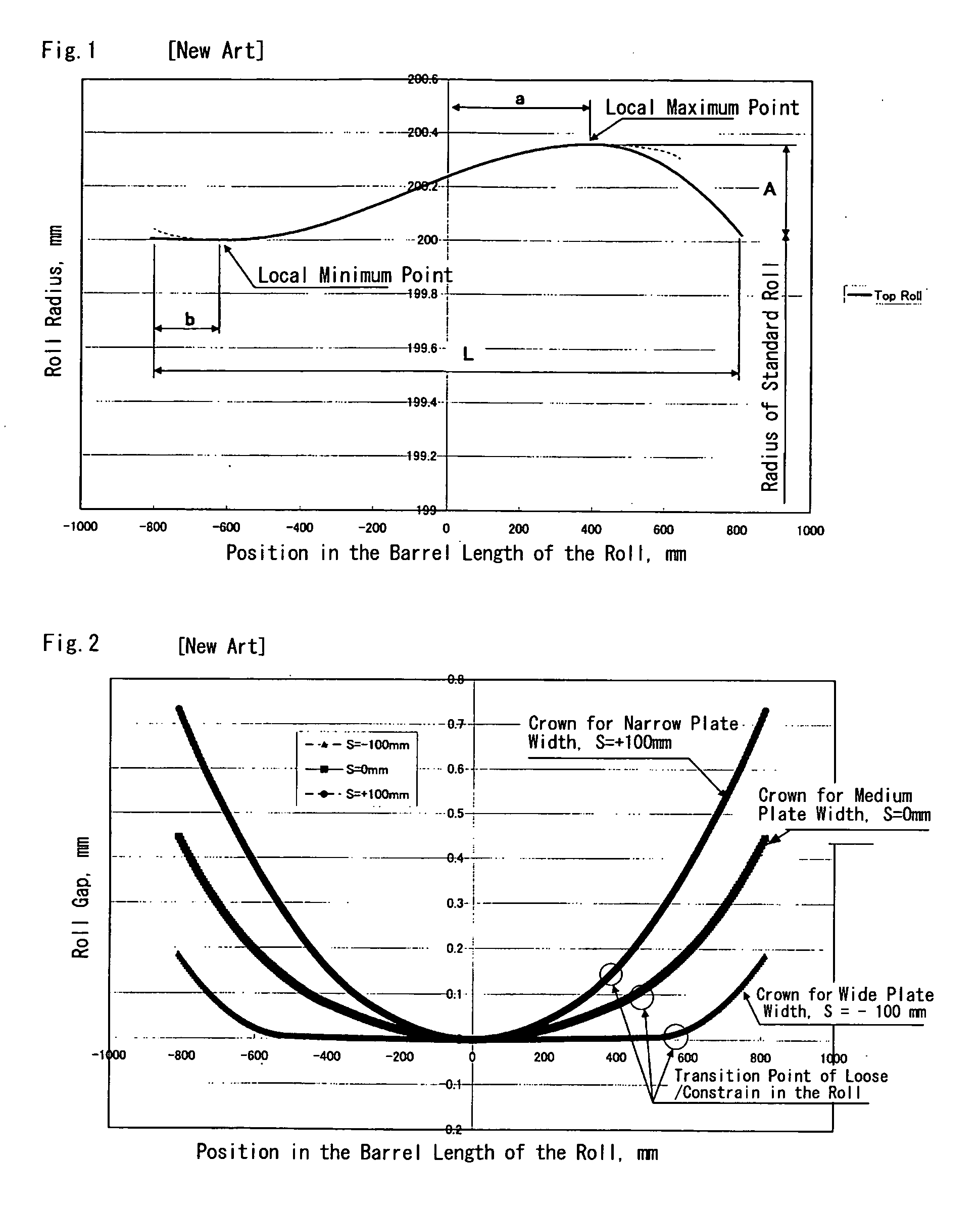
[0070]The following description is an example of the roll curve shown in FIG. 1.

[0071]Let L be a barrel length, a the distance of the local maximum point from the center of the barrel length of the roll, b the distance of the local minimum point from the end of the barrel length of the roll, and A the difference of the radius of the local maximum point and the local minimum point.

[0072]When the roll radius f (X′) on each point of the surface is composed of a cosine function with amplitude A between the local minimum point and the local maximum point, the roll curve between them is represented by the equations (a) and (2) such as:

X′=π / (L / 2+a−b)*(X−b)   (1)

f(X′)=−A / 2*COS (X′)+R0   (2)

[0073]R0: Standard roll radius

[0074]X represents the arbitrary axial position from the end of the roll barrel, but in FIG. 1 the center is regarded as 0 for convenience of illustrating.

[0075]The region from the end of the roll barrel to the local minimum point represents the following quadratic equation w...


PUM

PropertyMeasurementUnit
widthaaaaaaaaaa
widthaaaaaaaaaa
widthaaaaaaaaaa

Abstract

To provide a roll, a rolling mill and rolling method capable of not only effectively correcting the plate crown of a material to be rolled but also reducing the edge drop and preventing a roll from damage caused by the increase of the local line pressure between the rolls.
A roll crown is formed by a continuous curve having a local maximum point and a local minimum value point where the central region held between the local maximum point and the local minimum point represents one function and the end region from the local maximum point to the nearer roll end represents another function having an inclination of steeper gradient (or having a radius decreasing more sharply toward the roll end) than that of the extension of the function in the central region.

Description

TECHNICAL FIELD[0001]The present invention relates to a roll, a rolling mill and a rolling method, in rolling a metal plate as material, either in hot or cold processes, correcting the plate crown etc.BACKGROUND OF THE INVENTION[0002]When rolling metal plate by means of a rolling mill, the deflection of the roll caused by the rolling load may often generate the so-called plate crown: a phenomenon that the thickness of the part near the center (in the width direction) of the plate becomes greater than that of the part near the end (in the width direction) of the plate.[0003]One of rolling mills capable of correcting the plate crown is disclosed in the patent document 1. The rolling mill has the upper and lower work-rolls (or intermediate rolls or backup rolls) which are provided with an S-shaped roll crown, which may be called CVC or others, on the periphery, as shown in FIG. 8, and the pair of rolls relatively move (or shift against each other) in the axial direction. The relative m...

Claims


Application Information

Patent Timeline
Patent Type & Authority Applications(United States)
IPC IPC(8): B21B39/20
CPCB21B13/142B21B2027/022B21B27/021B21B27/02B21B13/14B21B37/42
Inventor KIKKAWA, TANEHIRO
Owner JP STEEL PLANTECH
Why Eureka
Try Eureka