
Intra-cycle variable step-length roll shifting control method for work rolls in downstream stands of hot rolling

A control method and technology of work rolls, applied in the direction of rolling mill control devices, rolls, metal rolling, etc., can solve the problems of uneven contact frequency distribution between strip steel and work rolls, increased cat ear height, and increased wear, and achieve effective It is beneficial to uniform wear, reduce height, and uniform wear roll shape

Active Publication Date: 2019-03-01
UNIV OF SCI & TECH BEIJING
View PDF7 Cites 0 Cited by
  • Summary
  • Abstract
  • Description
  • Claims
  • Application Information

AI Technical Summary

Problems solved by technology

[0004] 1. All roll shifting control methods are limited to equal step lengths in a single cycle, but this roll shifting control method leads to uneven contact frequency distribution between strip steel and work rolls at different positions within the entire roll period
For a long time, whether the step size can be changed in a single cycle has not been considered in this field, and how the step size changes;
[0005] 2. In the current roll shifting control method, the repetition of the roll shifting value will inevitably lead to an increase in the amount of wear at this position, which will inevitably lead to an increase in the height of the cat ears. However, all the above-mentioned roll shifting control methods have not faced this problem squarely or proposed solutions to this problem. train of thought

Method used


Image

  • Intra-cycle variable step-length roll shifting control method for work rolls in downstream stands of hot rolling

Examples


Embodiment Construction

[0035] In order to make the technical problems, technical solutions and advantages to be solved by the present invention clearer, the following will describe in detail with reference to the drawings and specific embodiments.

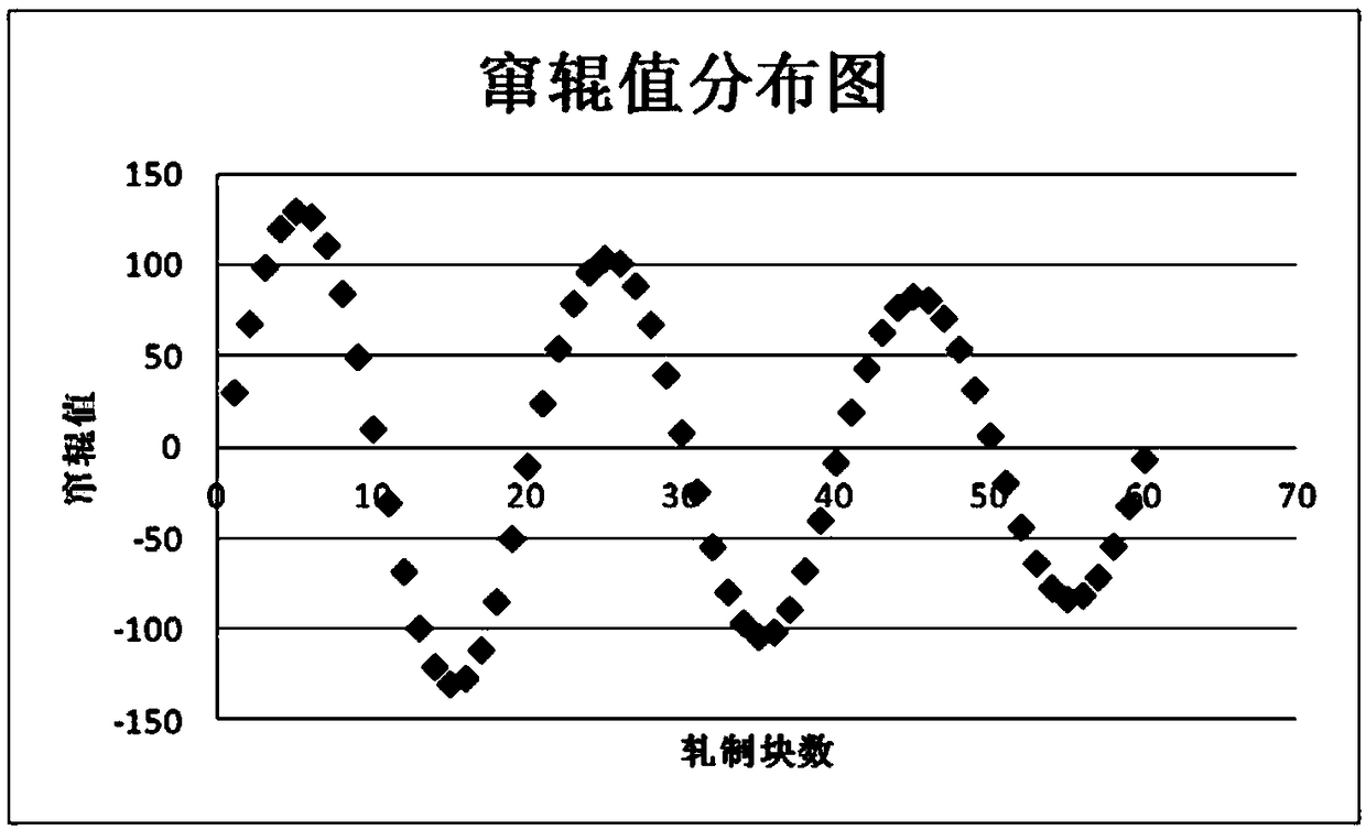
[0036] The invention provides a method for controlling roll shifting with variable step length within a cycle for the work rolls of the downstream stand of hot rolling. The method is used in the rolling of metal plates and strips. Move the same distance, and then roll the next piece of rolling, that is, roll shifting; during the strip rolling production process, the upper and lower work rolls periodically reciprocate between the forward and reverse maximum roll shifting stroke positions Roll, that is, after each piece of rolling is rolled, the roll shifting is carried out according to the predetermined step length. After reaching the forward or reverse maximum roll shifting stroke position, the direction of the upper and lower working rolls is reversed, a...


PUM


Abstract

The invention provides an in-cycle variable-step-length roll shifting control method targeted to hot rolling downstream rack work rolls and belongs to the technical field of hot rolling roll shifting control. According to the method, after each rolled piece is rolled, roll shifting is performed according to the preset step length, after the largest roll shifting stroke position in the positive direction or the reverse direction is reached, the roll shifting direction of the upper work roll and the roll shifting direction of the lower work roll are all reversed, the superposition position of the upper work roll and the lower work roll is served as the start point, the process of passing through the largest roll shifting stroke position in the positive direction once and the largest roll shifting stroke position in the reverse direction once and then returning to the superposition position of the upper work roll and the lower work roll again is served as a single reciprocating roll shifting cycle, and the variable roll shifting step length is adopted in the roll shifting cycle. By means of the roll shifting control method, on one hand, distribution of roll shifting values can be as uniform as possible in the whole roll shifting cycle, and it is beneficial to homogenized roll wear; and on the other hand, the same roll shifting value in the roll shifting cycle can be avoided, the roll wear is further homogenized, therefore the problems of subsequent rolled edge dropping and wave shape increasing caused by the worn roll shape are reduced, and the rolling kilometer number is increased.

Description

technical field [0001] The invention relates to the technical field of roll shifting control in hot rolling, in particular to a method for controlling roll shifting with variable step length within a cycle for working rolls in a downstream stand of hot rolling. Background technique [0002] The development of roll shifting control methods has experienced two stages: equal parameter roll shifting and variable parameter roll shifting. Equal parameter roll shifting refers to periodic reciprocating roll shifting by maintaining a fixed roll shifting stroke, roll shifting step size and roll shifting frequency throughout the rolling cycle. Variable parameter roll shifting refers to the roll shifting control method in which the roll shifting stroke, roll shifting step size and roll shifting frequency change during the entire roll shifting process. Variable step size roll shifting control method. [0003] From the original equal stroke roll shifting control method to the current op...

Claims


Application Information

Patent Timeline
Patent Type & Authority Patents(China)
IPC IPC(8): B21B37/00
CPCB21B37/00B21B2267/24B21B2269/14
Inventor 王晓晨杨荃孙西佳孙友昭徐冬刘洋何海楠赵剑威李宝鑫肖佳乐
Owner UNIV OF SCI & TECH BEIJING
Learn More