Communication apparatus, relay apparatus, communication system, communication method, and communication program

a technology of relay apparatus and communication system, applied in the field of communication control, can solve the problems of affecting the life of equipment, affecting the degree of freedom in communication, and unnecessary power consumption, so as to maintain communication reliability and reduce power consumption

Inactive Publication Date: 2008-02-21
FUJITSU LTD
View PDF31 Cites 60 Cited by
  • Summary
  • Abstract
  • Description
  • Claims
  • Application Information

AI Technical Summary

Benefits of technology

[0011]An object of the present invention relates to a communication apparatus equipped with a plurality of interfaces serving a plurality of networks, which communication apparatus selects an interface according to an electric wave reception intensity level to reduce power consumption and contribute to the maintenance of reliability in communication.

Problems solved by technology

In operating a communication apparatus equipped with a plurality of interfaces, current supply to every interface results in unnecessary power consumption.
For portable equipment powered by a battery, such unnecessary power consumption affects the life of the equipment significantly.
Stopping power supply to an interface on rest, however, disables the interface from communication, thus hampering a degree of freedom in communication.
This results in power supply to both high-frequency units when communication is carried out using the other high-frequency unit, which puts a limit on a reduction in power consumption.
Insufficient reception intensity, therefore, makes communication impossible.
Japanese Patent Application Laid-Open Publication No. 2005-73078, however, discloses or hints no solution to achieve such a goal.

Method used


Image

  • Communication apparatus, relay apparatus, communication system, communication method, and communication program
  • Communication apparatus, relay apparatus, communication system, communication method, and communication program
  • Communication apparatus, relay apparatus, communication system, communication method, and communication program

Examples


first embodiment

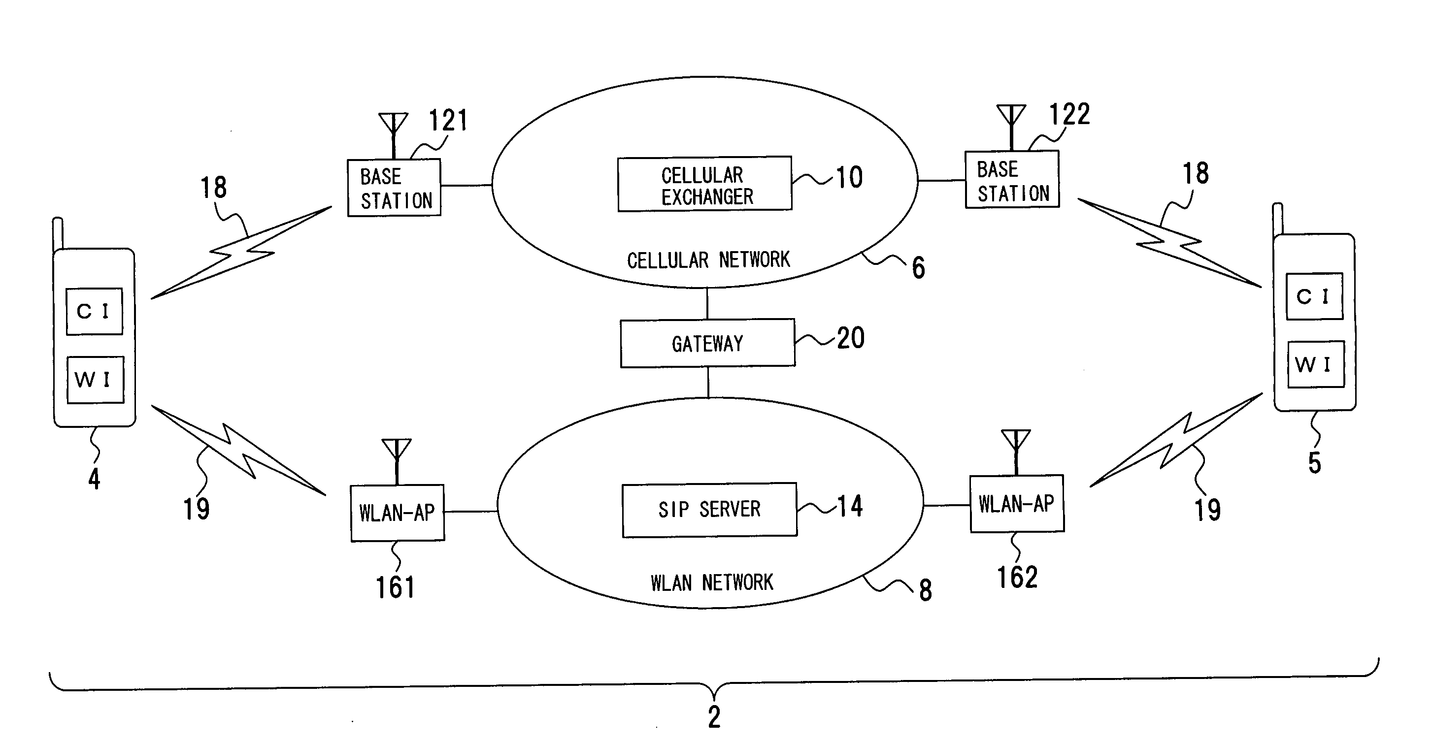
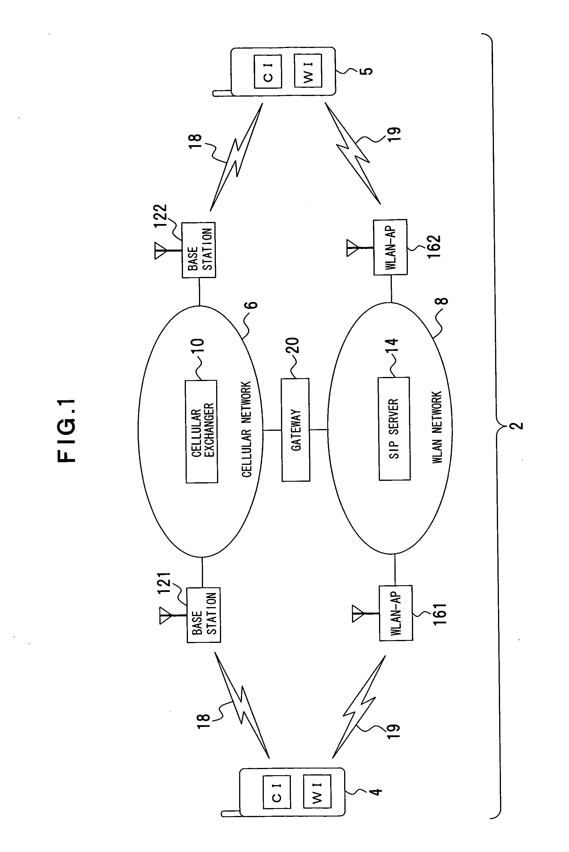
[0062]A first embodiment of the present invention will now be described with reference to FIG. 1. FIG. 1 depicts a communication system to which the present invention applies.

[0063]As shown in FIG. 1, the communication system 2 includes a communication apparatus, which is, for example, a communication terminal apparatus 4, and a plurality of communication lines (network), which are, for example, a cellular network 6 and an Internet-based network, such as wireless LAN (Wireless Local Area Network: WLAN). The communication system 2 is constructed as a system capable of communication through the cellular network 6 or the WLAN network 8. The communication system 2 offers a wider range of communication by operating in such a way that connection of a cellular interface CI and of a WLAN interface WI to a power supply is changed at the communication terminal apparatus 4 according to a communication condition of electric wave reception intensity, etc., and that either cellular network 6 or W...

second embodiment

[0127]A second embodiment according to the present invention will now be described referring to FIGS. 26, 27, 28 and 29. FIG. 26 depicts a structural example of a communication terminal apparatus 4 according to the second embodiment. FIG. 27 is a flowchart of a process procedure according to a communication program of the communication terminal apparatus 4 of the second embodiment. FIG. 28 is a flowchart of a subroutine on a call change. FIG. 29 is a flowchart of a subroutine on a process of a request for a call change sent to the network side. In FIG. 26, the same components as described in FIG. 4 are denoted by the same reference numerals to omit repeated descriptions.

[0128]According to the second embodiment, in the cellular interface CI of the communication terminal apparatus 4, the cellular RF front end unit 24 is connected to the power controlling unit 38 via a power feeder cable 341, and the cellular base band unit 26 is connected to the power controlling unit 38 via a power f...

third embodiment

[0146]A third embodiment according to the present invention will now be described referring to FIG. 30. FIG. 30 is a flowchart of a process procedure of a communication terminal apparatus 4 according to the third embodiment.

[0147]The communication terminal apparatus 4 of the third embodiment has the same structure as the communication terminal apparatus 4 of the second embodiment (FIG. 26). The cellular RF front end unit 24 and the WLAN-RF front end unit 30 are connected constantly to the power supply, and connection of the cellular base band unit 26 or the WLAN base band unit 32 to the power supply is changed according to a communication state, such as electric wave reception intensity.

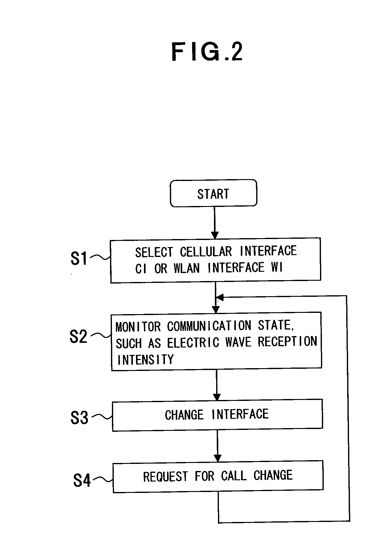
[0148]The third embodiment, in the same manner as the first embodiment, is implemented by using the communication system 2 shown in FIG. 1, the communication method shown in FIGS. 2 and 3, the cellular exchanger 10 shown in FIG. 7, the SIP server 14 shown in FIG. 9, and the gateway 20 shown in FIG. 1...


PUM


Abstract

A communication apparatus has a plurality of interfaces serving a plurality of networks. The communication apparatus selects an interface according to electric wave reception intensity to reduce power consumption and contribute to the maintenance of reliability in communication. The communication apparatus (communication terminal apparatus, the other party's communication terminal apparatus) is used for communication in such a way that the communication apparatuses are connected to the plurality of networks wirelessly to carry out communication through each network. The communication apparatus has the plurality of interfaces (cellular interface CI, WLAN interface WI) responding to the networks. The communication apparatus also has controlling unit (power supply controlling unit) that connects any one of the interfaces to the power supply to actuate the connected interface, and that connects an interface on rest to the power supply in response to a communication state of an interface on communication to change communication connection from the interface on communication to the other interface on rest. The communication apparatus changes the interfaces while maintaining communication with the other party's communication apparatus.

Description

CROSS-REFERENCE TO RELATED APPLICATIONS[0001]This application is based upon and claims the benefit of priority from the prior Japanese Patent Application No. 2006-208998, filed on Jul. 31, 2006, the entire contents of which are incorporated herein by reference.BACKGROUND OF THE INVENTION[0002]1. Field of the Invention[0003]The present invention relates generally to communication control including a plurality of interfaces such as an interface serving a WLAN (Wireless Local Area Network) and an interface serving a cellular network and provided in response to a communication state such as electric wave reception intensity, and more particularly, to a communication apparatus, a server, a relay apparatus, a communication system, a communication method, a communication program, and a recording medium that selects an interface to execute detoured incoming call reception.[0004]2. Description of the Related Art[0005]Communication using mobile equipment including a cellular phone is carried ...

Claims


Application Information

Patent Timeline
Patent Type & Authority Applications(United States)
IPC IPC(8): G06F15/16H04B1/3822H04B1/40H04W36/12H04W36/36H04W48/16H04W48/18H04W52/02H04W84/12H04W88/06H04W88/08H04W88/16
CPCH04W36/0022H04W36/14H04W36/30Y02B60/50H04W52/0245H04W88/06H04W36/36H04W36/305Y02D30/70
Inventor SANO, SHOICHI
Owner FUJITSU LTD
Why Eureka
Try Eureka